
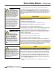
Instruction Manual

Printed in USA 07/06 P/N 50165 rev. D
Machine Safety Switches
®
SI-LS31H Series 31 mm Limit-Switch-Style with Hinged Lever Actuators
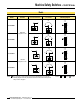
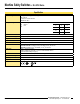
Model Actuator
Contact Configuration
(Lever in Normal Position)
Contact Configuration
(Lever Rotated)
Switching Diagram
SI-LS31HGD
Vertical Hinged
Lever ±90°
SI-LS31HGE
Contacts: Open Closed Transition
Models
NOTE: This symbol for a positive opening safety contact (IEC 60947-5-1) is used in the
switching diagrams to identify the point in actuator travel where the normally closed
safety contact is fully open.
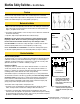
Features
• Limit switch design (EN 50047)
• For use on doors or flaps
•
Positive opening safety contacts (IEC 60947-5-1) (not dependent upon springs)
• Glass-reinforced thermoplastic switch housing with plated steel actuator
• Insulated device (IEC 60947-5-1) on all models with plastic housings
• Actuator head rotatable in 90 degree increments
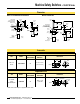
23 24
11 12
0°
23 24
11 12
0°
90°90°
±8°
±5°
0°
±10°
±90°
11-12
23-24
Safety
Monitor
21 22
11 12
0°
21 22
11 12
0°
90°90°
±8°
±5°
0°
±90°
11-12
21-22
Safety
Monitor
Safety