
Manual

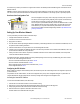


5-pin Euro-Style Hookup
Wiring the 5-pin Euro-style connector depends on the model and power requirements of the device. Connecting dc power to the commu-
nication pins will cause permanent damage.
Wire No. Wire Color Description
1
2
3
4
5
1 Brown 10 to 30V dc
2 White RS485 / D1 / B / +
3 Blue dc common (GND)
4 Black RS485 / D0 / A / –
5 Gray Comms Gnd
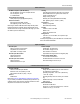
Terminal Block
PWR
GND
DO4
DI4
PWR
GND
DO2
DI2
PWR
GND
DO3
DI3
PWR
GND
DO1
DI1
DIx. Discrete IN x.
DOx. Discrete OUT x.
GND. Ground/dc common connection.
PWR. Power, 10 to 30V dc power connection.
Wiring Diagrams for Discrete Inputs
Connecting dc power to the communication pins will cause permanent damage. For the DX8x...C models, PWR in the wiring diagram
refers to V+ on the wiring board and GND in the wiring diagram refers to V- on the wiring board.
Discrete Input Wiring for PNP Sensors Discrete Input Wiring for NPN Sensors
DIx
PWR
10-30V dc
DIx
GND
dc common
Wiring Diagrams for Discrete Outputs
Connecting dc power to the communication pins will cause permanent damage. For the DX8x...C models, PWR in the wiring diagram
refers to V+ on the wiring board and GND in the wiring diagram refers to V- on the wiring board.
Discrete Output Wiring (PNP)
DOx
GND
PWR
10-30V dc
Load
dc common
SureCross DX80 Gateway
4 www.bannerengineering.com - tel: 763-544-3164 P/N 131291 Rev. F