
Instruction Manual
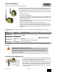
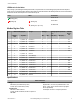

LED Behavior for the Nodes
After powering up and binding the Gateway and its Nodes, verify all devices are communicating properly. A Node will not sample its
inputs until it is communicating with its Gateway. When testing communication between the Gateway and Node, all radios and antennas
should be at least two meters apart or the communications may fail.
LED 1 LED 2 Node Status
(flashing green)
Radio Link Ok
(flashing red) (flashing red)
Device Error
(flashing red, 1 per 3 sec)
No Radio Link
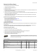
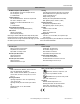
Modbus Register Table
I/O
Modbus Holding Register I/O Type I/O Range Holding Register Representa-
tion
Terminal
Block La-
bels
Gateway /
DX85
Any Node Min. Max. Min. (Dec.) Max. (Dec.)
1 1 1 + (Node# × 16) Discrete IN 1 0 1 0 1 DI1
2 2 2 + (Node# × 16) Discrete IN 2 0 1 0 1 DI2
3 3 3 + (Node# × 16) Discrete IN 3 0 1 0 1 DI3
4 4 4 + (Node# × 16) Discrete IN 4 0 1 0 1 DI4
5 5 5 + (Node# × 16) Discrete IN 5 0 1 0 1 DI5
6 6 6 + (Node# × 16) Discrete IN 6 0 1 0 1 DI6
7 7 7 + (Node# × 16) Reserved
8 8 8 + (Node# × 16) Device Message
9 9 9 + (Node# × 16) Discrete OUT 1 0 1 0 1 DO1
10 10 10 + (Node# × 16) Discrete OUT 2 0 1 0 1 DO2
11 11 11 + (Node# × 16) Discrete OUT 3 0 1 0 1 DO3
12 12 12 + (Node# × 16) Discrete OUT 4 0 1 0 1 DO4
13 13 13 + (Node# × 16) Discrete OUT 5 0 1 0 1 DO5
14 14 14 + (Node# × 16) Discrete OUT 6 0 1 0 1 DO6
15 15 15 + (Node# × 16) Control Message
16 16 16 + (Node# × 16) Reserved
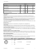
Specifications
Radio and General
Range
900 MHz: Up to 4.8 kilometers (3 miles)
2.4 GHz: Up to 3.2 kilometers (2 miles)
Transmit Power
900 MHz: 21 dBm conducted
2.4 GHz: 18 dBm conducted, less than or equal to 20
dBm EIRP
Power
Requirements: +10 to 30V dc (Outside the USA: +12 to
24V dc, ±10%). (See UL section below for any applica-
ble UL specifications)
Consumption: Less than 1.4 W (60 mA) at 24V dc
SureCross DX80 Node
P/N 132162 Rev. H www.bannerengineering.com - tel: 763-544-3164 5