SureCross User Configuration Tool (UCT) Rev.
Contents Contents SureCross User Configuration Tool Installation ........................................................................................................3 ............................................................................................................................................................................3 The UCT Screens ......................................................................................................................................
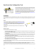
SureCross User Configuration Tool The User Configuration Tool (UCT) offers an easy way to link I/O points in your wireless network, view I/O register values graphically, and set system communication parameters when a host system is not part of the wireless network. The UCT requires a special USB to RS-485 (model number BWA-UCT-900 for 1 Watt radios, BWA-HW-006 can be used for all other radios) converter cable to pass information between your computer and the Gateway.
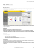
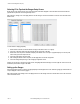
SureCross User Configuration Tool (UCT) The UCT Screens Register View Use the Register View screen to graphically display specified Node I/O values. Up to three values can be graphically displayed as either a dial, a thermometer, or a discrete on/off status. To begin configuring your graphic displays, click on the Settings button. A setup screen with three tabs opens. To configure your graphical displays, begin with the I/O Setup tab.
SureCross User Configuration Tool (UCT) Selecting I/O to Populate the Gauges Setup Screen Nodes and I/O points selected on this screen control the register information displayed on the main Status screen and what devices populate the drop-down lists on the Gauges Setup screen. After making any changes, click on the Apply button to save the changes. Click on the OK button to close this screen and return to the Status screen. To select a Node to display graphically: 1.
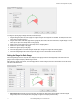
SureCross User Configuration Tool (UCT) To configure a specific gauge to display information, follow these steps: 1. Using the Gauge drop-down list, select a gauge to configure. Gauges one through three are available. The example shown in the screen image is configuring gauge 1. 2. Using the radio buttons, select if this gauge will be a gauge dial, thermometer, tank level measurement, or digital display. You may select only one option. The example shown is using a gauge. 3.
SureCross User Configuration Tool (UCT) 2. Set the Minimum and Maximum values displayed on the gauge. Select the minimum and maximum values displayed on the gauge. In the example shown, this gauge is set to display from 0 to 100 percent relative humidity. 3. Establish the Major Tick Increment and the Minor Tick Count. The major tick increment establishes the incremental count for the gauge.
SureCross User Configuration Tool (UCT) Counter Enable. An enable byte that turns any input point into a synchronous counter. Set to 0 to turn off (default). Set to 1 to enable the 16-bit counter (report type must be set to analog). Set to 2 to enable the 32-bit counter (report type must be set to double). (Parameter number 0x18). The counter value is stored in the Modbus registers. For a 32-bit counter type, Modbus registers N and N+1 are used. Default Value (bits 15:0).
SureCross User Configuration Tool (UCT) Report Type (bits 1:0). Defines the internal data structure and reporting definition for an I/O point. If a discrete point changes state, all I/O points are reported to the Gateway in discrete values. An analog input can be treated as a digital value using the Threshold and Hysteresis parameters. (Parameter number 0x0E). • Discrete/bit report type = 0. Use for discrete values. • Analog report type = 1 (default). Use for all analog values (two bytes).
SureCross User Configuration Tool (UCT) The baseline threshold/filter parameter sets a baseline threshold and filter activation time on M-GAGE devices. When M-GAGE input readings are below the selected baseline threshold setting, the filter algorithm slowly lowers the magnetic baseline reading to zero to remove small changes in the magnetic field over time. Setting options include the following values: (Parameter number 0x13).
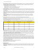
SureCross User Configuration Tool (UCT) Type # Hex Dec 0x31 49 0x32 0x33 Description Type # Hex Dec Analog IN 2 0x03 3 50 Analog IN 3 0x05 51 Analog IN 4 Description Type # Description Hex Dec NPN IN 2 0x1A 26 Multiple Discrete PNP 5 NPN IN 3 0x3B 59 SDI 12 COMMs 0x07 7 NPN IN 4 0xB1 177 Serial Read 0x1B 27 NPN IN 5 0xB2 178 Serial Write 0x0D 13 Async Counter 1 0x1D 29 NPN IN 6 0x37 55 Battery voltage 0x0E 14 Async Counter 2 0x1F 31 NPN IN 7 0xF0 24
SureCross User Configuration Tool (UCT) Type # Hex Dec 0x5C 92 0xBC Description Type # Description Hex Dec Thermistor IN 5 0x38 56 188 Thermocouple B1 0x39 0xBD 189 Thermocouple B2 0xBE 190 0x50 Type # Description Hex Dec Thermocouple K1 0xD7 215 Thermocouple S1 57 Thermocouple K2 0xD8 216 Thermocouple S2 0x3A 58 Thermocouple K3 0xD9 217 Thermocouple S3 Thermocouple B3 0x4E 78 Thermocouple K4 0x59 89 Thermocouple S4 80 Thermocouple B4 0xCB 203 Thermocoupl
SureCross User Configuration Tool (UCT) To view all the device's factory information: 1. Using the Device drop-down list, select a device to read manufacturing data from or send control commands to. 2. Click the Get Info button. The program retrieves all version and manufacturing data from the device and displays it on the screen. Default Output Conditions Default output conditions are the conditions that drive outputs to defined states.
SureCross User Configuration Tool (UCT) Device Restore To reset or restore a device: 1. Select a device from the dropdown list. 2. Select one of the function commands listed below. • Reset Device. Select the Reset Device checkbox to send a power-on reset command to the device selected by the Device dropdown list. • Restore Device I/O to Factory Defaults. Select the Restore Device I/O checkbox to send a restore I/O factory default command to the device selected by the Device dropdown list.
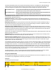
SureCross User Configuration Tool (UCT) Result Description Green Packets received at a strong signal strength. A strong signal strength is greater than −90 dBm at the receiver. Yellow Packets received at a good signal strength. A good signal is between −90 and −100 dBm at the receiver. Red Packets received at a weak signal strength. A weak signal is less than −100 dBm at the receiver. Missed Packets not received on the first transmission and requiring a retry.
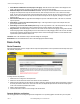
SureCross User Configuration Tool (UCT) Save Device Data To save the configuration file of a specific device: 1. Select the device from the dropdown list. 2. Click on the browse button to select a location and file name on your harddrive. 3. After the path and file name automatically fill in the File: box, click on the Save Device button to save the configuration file to the selected location on your harddrive. Load Device Data To load a saved configuration to a specific device: 1.
SureCross User Configuration Tool (UCT) signal strength between the Gateway and all Nodes. To analyze the signal strength between a single Node and the Gateway, right click on the Node in the list and select Get Signal Quality. I/O Mapping Use the I/O Mapping screen to easily map one SureCross device’s inputs to another SureCross device’s outputs, as long as both devices are part of the wireless network. To begin mapping your I/O: 1. Select the source device from the drop-down menu.
SureCross User Configuration Tool (UCT) Default Output. If a default output is selected, this is the value placed in this register when radio communications are lost between the Gateway and this Node. Hold Last State. If this checkbox is selected, this register retains the last sampled state when radio communications are lost between the Gateway and this Node. Arrow Color. The color of the arrows indicates a specific system status.
SureCross User Configuration Tool (UCT) High Speed Synching: This mode allows DX80 Nodes to synchronize to the Gateway much faster, which causes more RF traffic from the Gateway and uses more operating current. We do not recommend using this setting in multiple network environments. Power Save Gateway: This mode is for applications that require minimizing the power consumption of the Gateway (battery or solarpowered). This setting causes higher latency in the communications between the Gateway and Node.
SureCross User Configuration Tool (UCT) Misses’ for that Node. If the ‘Maximum Misses’ is exceeded for any Node, the Gateway generates an RF timeout error in the Modbus I/O register 8 of the appropriate Node. The ‘Maximum Misses’ is defined as the number of consecutive polling messages that the Node fails to respond to. is a calculated value from Polling Interval (sec) × Maximum Misses. Heartbeat Configuration Use this screen to set the system-wide Heartbeat parameters.
SureCross User Configuration Tool (UCT) To set the system health parameters for each device: 1. 2. 3. 4. 5. Use the drop-down list to select the appropriate Node. Select one of the health options: heartbeat, polling (power save ON), or polling (power save OFF). Click on the Send button to send these parameters changes to the selected Node. Repeat steps one through three for each Node in the network.
SureCross User Configuration Tool (UCT) The Get button reads the current master table in the Gateway. The Send button sends the user defined table to the Gateway. The Clear button sets all master fields in the User Configuration Tool to zero. Clicking the Clear button does not affect the table entries stored in the Gateway. Master Table Map Number. There are 32 possible table entries in the master table. The map number is only an index into the master table. Local Register.
SureCross User Configuration Tool (UCT) 2. Click the Send button to send the master table data to the Gateway. 3. Select the radio button for DX80 is Modbus RTU Master 4. Click the Change Mode button After the Master Timeout time expires, the Gateway becomes the Modbus master device and begins executing the master table entries. To change the Gateway to a Modbus slave device: 1. Turn off the power to the Gateway 2. Turn on the power to the Gateway. 3.
SureCross User Configuration Tool (UCT) Example Configuration To configure Analog IN 1 for a specific sample rate, report rate, and switch power output voltage, follow these steps. For this specific configuration example, we will be using a DX80N9X2S-P1 SureCross Performance Node. Configuring other Node models is the same, except that the input point associated with Analog IN 1 may be different. 1. To use the UCT to configure your Node, first set the Node's DIP switch to be Host Configured.
SureCross User Configuration Tool (UCT) 6. Click on the Send button to send this setting to the Gateway's configuration file. Configuring the Sample Rate 1. Use the Device Parameters screen to set the sample rate. In this example, we are setting the sample rate of input 3 (Analog IN 1) to 30 minutes (28,800 62.5 ms intervals). 2. Click on the Send button to send this setting to the Gateway's configuration file. Configuring the Report Rate 1. Use the Device Parameters screen to set the report rate.
SureCross User Configuration Tool (UCT) Advanced Topics Units Defined The units parameter defines the range and/or type of data value associated with an input or output. Selecting Units from within any configuration tool changes the units definition of several parameters, including threshold, hysteresis, and delta. For example, if the units are 0-20 mA, the threshold, hysteresis, and delta values are entered as milliampere values.
SureCross User Configuration Tool (UCT) Units Description Definition LCD: 0000.0F 10 11 Asynchronous Counter, 32-bit The 32-bit counter value records counts up to 4.29 billion. Asynchronous Counter, 16-bit The 16-bit counter value records counts up to 65535. LCD: 0000 0000 LCD: 0000 Output Units Units 0 Description Definition Raw Displays the raw A/D conversion data with data ranges from 0 to 65535. This units type is typically used only for factory calibration.
SureCross User Configuration Tool (UCT) Units 9 Description Definition Signed Analog, 4 to 20 mA (B) In older models, this units type is for degree Fahrenheit conversions only. Use null to set the start point and span to define the range. The null value is the starting temperature to be associated with 4 mA. The span is the entire temperature range that is to be associated with 4 to 20 mA. For newer firmware models, type codes 8 and 9 are treated the same. LCD: 4.00mA–20.
SureCross User Configuration Tool (UCT) • In high resolution mode, the temperature = (Modbus register value)÷20. For high resolution temperature input, 0 in the register is interpreted as 0° and 65535 in the register (0xFFFF) is interpreted as −1 ÷ 20 = −0.05°. • In low resolution mode, the temperature is (Modbus register value)÷2. For low resolution temperature input, 0 in the register is interpreted as 0° and 65535 in the register (0xFFFF) is interpreted as −1 ÷ 2 = −0.5°.
SureCross User Configuration Tool (UCT) Output Scale Fullscale (range) Offset 0 to 10V 10V 0V Fullscale. Defined in the table; the output range. Span. The total range of values mapped to the output. Null. The starting point for the output scale. Input Value. The value mapped to the output. Offset. Defined in the table; the starting output value. Example: Temperature Map Map a temperature input from a Node to a 4–20 mA output.
Index D default value 7, 9–12 delta 7, 9–12 duty cycle 7, 9–12 F P parameter numbers 7, 9–12 power supply 7, 9–12 pulse width 7, 9–12 fullscale 28, 29 R G report rate 7, 9–12 report type 7, 9–12 gauges configuring 4–6 S H samples low/high 7, 9–12 span 28, 29 switch power voltage 7, 9–12 hysteresis 7, 9–12 T I input value 28, 29 invert flag 7, 9–12 N threshold 7, 9–12 U units conversion 28, 29 null 28, 29 O offset 28, 29 Rev.