SureCross™ Wireless I/O Network Product Manual Printed in USA Feb 2012 P/N 132607 rev.
Banner Engineering Corp. 9714 Tenth Ave. No. Minneapolis, MN USA 55441 Phone: 763.544.3164 www.bannerengineering.com Email: sensors@bannerengineering.com Banner Engineering Corp. warrants its products to be free from defects in material and workmanship for one year following the date of shipment. Banner Engineering Corp. will repair or replace, free of charge, any product of its manufacture which, at the time it is returned to the factory, is found to have been defective during the warranty period.
Table of Contents Introducing the SureCross™ Wireless System . . . . . . . . . . . . . . . . . . . . . . . . . . . . . . . . . . . . . . . . . . . . . . . . . . . . . . . . . . . . . . . . . . . . 5 Features . . . . . . . . . . . . . . . . . . . . . . . . . . . . . . . . . . . . . . . . . . . . . . . . . . . . . . . . . . . . . . . . . . . . . . . . . . . . . . . . . . . . . . . . . . . . . . . . 6 Pinouts . . . . . . . . . . . . . . . . . . . . . . . . . . . . . . . . . . . . . . . . . . . . . . . . . .
Introduction SureCross Wireless Network Product Manual Serial Communication (RS-232 or RS-485) . . . . . . . . . . . . . . . . . . . . . . . . . . . . . . . . . . . . . . . . . . . . . . . . . . . . . . . . . . . . . . . . . . . . . 83 Antennas and Accessories . . . . . . . . . . . . . . . . . . . . . . . . . . . . . . . . . . . . . . . . . . . . . . . . . . . . . . . . . . . . . . . . . . . . . . . . . . 84 Antennas . . . . . . . . . . . . . . . . . . . . . . . . . . . . . . . . . . . . . . . . . . .
SureCross Wireless Network Introduction Product Manual Introducing the SureCross™ Wireless System The SureCross™ DX80 wireless I/O network provides reliable monitoring without the burden of wiring or conduit installation and can operate independently or in conjunction with a PLC and/or PC software. The SureCross Network The SureCross DX80 network is a deterministic system—the network identifies when the radio signal is lost and drives relevant outputs to user-defined conditions.
SureCross Wireless Network Introduction Product Manual Features DX80 Gateway and Node 1 2 3 4 5 6 7 1. Port, NPT Gland, or Plug If unused, install the provided plug into the 1/2 NPT threaded port. Refer to the Installation section if an IP67 seal is required. 2. Rotary Switch 1 (left) Sets the Network ID (NID) to a hexidecimal value from 0 to F, for a total of 16 Network IDs. A Gateway and its corresponding Nodes must be assigned the same Network ID.
SureCross Wireless Network Introduction Product Manual DX80 GatewayPro 1 2 3 4 5 6 7 1. Industrial Ethernet Port, female 2. Rotary Switch 1 (left) Sets the Network ID (NID) to a hexidecimal value from 0 to F, for a total of 16 Network IDs. A Gateway and its corresponding Nodes must be assigned the same Network ID. Rotary Switch 2 (right) Gateway: Sets the Gateway’s LCD viewing device address. The Gateway is predefined as Device Address 0.
SureCross Wireless Network Introduction Product Manual DX83 Ethernet Bridge 1 2 3 1. Industrial Ethernet Port, female 2. Housing The rugged, industrial DX80 housing meets IEC IP67 standards. 3. Mounting Hole, #10/M5 Clearance Mounting Holes accept metric M5 or UNC/UNF #10 hardware -- DIN rail mount adapter bracket available. 4.
SureCross Wireless Network Introduction Product Manual Pinouts Wire Color 10 to 30V dc Powered Node 1 Brown 2 White 3 Blue 4 Black 5 Gray Battery Powered Node +10 to 30V dc Input dc common (GND) dc common (GND) 3.6 to 5.5V dc For FlexPower devices, do not apply more than 5.5V dc to the gray wire.
SureCross Wireless Network Introduction Product Manual Dimensions DX80 Gateway and Node 65.0 [2.56”] 22.2 [0.875”] 7.9 [0.31”] 30.65 [1.21”] 65.0 [2.56”] 19 [0.75”] 80.3 [3.16”] 127 [5”] 7.65 [0.30”] 60 [2.36”] 14.67 [0.578”] 80.8 [3.18”] 120 [4.72”] 10 Banner Engineering Corp. • Minneapolis, MN U.S.A. www.bannerengineering.com • Tel: 763.544.
SureCross Wireless Network Introduction Product Manual DX80 GatewayPro 65.0 [2.56’’] 7.9 [0.31’’] 65.0 [2.56’’] 80.3 [3.16’’] 136 [5.35’’] 7.65 [0.30’’] 60 [2.36’’] 14.67 [0.578’’] 80.8 [3.18’’] Banner Engineering Corp. • Minneapolis, MN U.S.A. www.bannerengineering.com • Tel: 763.544.
SureCross Wireless Network Introduction Product Manual DX83 Ethernet Bridge 65.0 [2.56’’] 7.9 [0.31’’] 65.0 [2.56’’] 80.3 [3.16’’] 136 [5.35’’] 7.65 [0.30’’] 60.0 [2.36’’] 14.67 [0.578’’] 80.8 [3.18’’] 12 Banner Engineering Corp. • Minneapolis, MN U.S.A. www.bannerengineering.com • Tel: 763.544.
SureCross Wireless Network Introduction Product Manual Menu Structure DX80 Gateway and GatewayPro Setup Menu When power is applied, the DX80 begins running. The display screen auto loops through the RUN menu and communication begins between the Gateway and Node(s). Auto looping through the RUN menu is the normal operating mode for all devices on the wireless network. From the RUN Menu (or any menu), single-click button 1 to advance through the top-level menus.
SureCross Wireless Network Introduction Product Manual DX80 Node Setup Menus When power is applied, the DX80 begins running. The display screen auto loops through the RUN menu and communication begins between the Gateway and Node(s). Auto looping through the RUN menu is the normal operating mode for all devices on the wireless network. From the RUN Menu (or any menu), single-click button 1 to advance through the top-level menus.
SureCross Wireless Network Product Manual Introduction RUN The RUN menu displays the Network ID, device name, and the I/O values of the device. On a Gateway, the I/O displayed may be the I/O of the Gateway or of a selected Node, which is determined by the position of the rotary switches. DINFO (Device Information) The Device Info menu displays the device-specific information, such as the device name, the Network ID, Slave ID, baud rate, and parity.
SureCross Wireless Network Basic Setup Product Manual Setting Up Your Wireless Network Step 1: Use Extended Address Mode Extended address mode assigns a unique code, the extended address code, to all devices in a particular network, thereby controlling which radios can exchange information. Using extended address mode isolates networks from one another by assigning a unique code, the extended address code, to all devices in a particular network.
SureCross Wireless Network Basic Setup Product Manual Step 2: Apply Power 1. Apply power to the Gateway by connecting the 10-30V dc cable as shown in the wiring diagram. The Gateway begins in *RUN mode, displays the current network ID (NID), then identifies itself as a Gateway. 2. Apply power to the Node by connecting the 10-30V dc cable or the DX81 Battery Supply Module as shown. The Node starts in *RUN mode, displays the current network ID, then identifies itself as a Node and lists the device ID.
SureCross Wireless Network Basic Setup If your Gateway has buttons Product Manual OR Triple click button 2 to enter binding mode. The red LEDs flash alternately when the Gateway is in binding mode. Any Node entering binding mode will bind to this Gateway. The LCD shows NETWRK BINDNG. If your Gateway does not have buttons Remove the rotary dial access cover and set both the right and left rotary dials to 0, then set both the right and left rotary dials to F.
SureCross Wireless Network Basic Setup Product Manual Step 4: Verify Communications On the Gateway Verify LED 1 is on and green. On the Node Verify LED 1 is flashing green and LED 2 is off. Until communication is established with the Gateway, the Node’s LED 2 flashes red. When communication is established, the Node’s LED 1 flashes green. A Node will not sample its inputs until it is in sync with a Gateway.
SureCross Wireless Network Site Survey Product Manual Site Survey Conducting a Site Survey analyzes the radio communications link between the Gateway and any Node within the network by reporting the number of missed and received data packets. Perform the Site Survey before permanently installing the radio network to ensure reliable communication. Activate Site Survey mode from either the Gateway buttons or the Gateway Modbus holding register 15.
SureCross Wireless Network Product Manual Site Survey Site Survey from the Menu System Use the Gateway to initiate a site survey analysis. Follow these steps to initiate a Site Survey using the Gateway’s buttons and menu system. On the Gateway 1. 2. Remove the rotary switch access cover. To check the status of Node 1, change the Gateway’s right rotary switch setting to 1. The Gateway is now enabled to read the status of Node 1; the display scrolls through the Node’s I/O status. 3. 4. 5.
SureCross Wireless Network Site Survey Product Manual Site Survey from Modbus Commands All DX80 models reserve the Modbus register I/O 15 (write only) for control messages. The control message code for the Site Survey command is listed below. To start a Site Survey using a Modbus write holding register command, send a control code of 32 (0x20) and the Node number 1–15 (0x01 to 0x0F) to the Gateway Modbus holding register for I/O 15.
SureCross Wireless Network Site Survey Product Manual Interpreting the Site Survey Results Site Survey results are listed as a percentage of data packets received and indicate the signal strength of the received signal. Result Green Description Packets received at a strong signal strength. A strong signal strength is greater than −90 dBm at the receiver. Yellow Packets received at a good signal strength. A good signal is between −90 and −100 dBm at the receiver.
SureCross Wireless Network Installation Product Manual Installation 24 Banner Engineering Corp. • Minneapolis, MN U.S.A. www.bannerengineering.com • Tel: 763.544.
SureCross Wireless Network Product Manual Installation Ideal Mounting Conditions Use a Secondary Enclosure For most outdoor applications, we recommend installing your SureCross devices inside a secondary enclosure. For a list of available enclosures, refer to the Accessories list. Mounting SureCross Devices Outdoors Without a Secondary Enclosure Avoid Direct Sunlight. To minimize the damaging effects of ultra-violet radiation, avoid mounting any SureCross™ device facing intense direct sunlight.
SureCross Wireless Network Installation Product Manual Weather-Proofing Glands and Plugs If the Gateway or Node is mounted outdoors or will be exposed to moisture, dirt, or dust, follow these steps to weatherproof the units. Watertight Glands To make the glands watertight: 1. Watertight Glands and Plugs Wrap four to eight passes of polytetrafluoroethylene (PTFE) tape around the threads as close as possible to the hexagonal body of the gland. 2. Manually thread the gland into the housing hole.
SureCross Wireless Network Installation Product Manual Quick Tips Create a Clear Communication Path Wireless communication is hindered by radio interference and obstructions in the path between the transmitter and receiver. To achieve the best radio performance, carefully consider the installation locations for the Gateways and Nodes and select locations without obstructions in the path. For more information about antennas, please refer to the Antenna Basics reference guide, Banner document p/n 132113.
SureCross Wireless Network Installation Product Manual Remote Antenna Installation When installing a remote antenna system, always include a lightning arrestor or coaxial surge suppressor in the system. Remote antenna systems installed without surge protection invalidate the Banner warranty of the DX80 family of devices. A remote antenna system is any antenna system where the antenna is not connected directly to the radio and typically use coaxial cable to connect the antenna to the radio.
SureCross Wireless Network Product Manual Installation Weatherproofing Remote Antenna Installations Prevent water damage to the cable and connections by sealing the connections with rubber splicing tape and electrical tape. To protect the connections, follow these steps. 1. Verify both connections are clean and dry before connecting the antenna cable to the antenna or other cable and hand-tightening. 2. Tightly wrap the entire connection with rubber splicing tape.
Advanced Setup SureCross Wireless Network Product Manual Advanced Setup 30 Banner Engineering Corp. • Minneapolis, MN U.S.A. www.bannerengineering.com • Tel: 763.544.
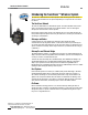
SureCross Wireless Network Advanced Setup Product Manual Ethernet Communications The DX80 wireless systems are configured using an Ethernet network connection and a common Web page browser. An Ethernet connection can be established from a DX80 GatewayPro device or a DX83 Ethernet Bridge device serially connected to the DX80 Gateway. The Ethernet Bridge and GatewayPro each ship with an Ethernet crossover cable. One end of the cable is a RJ45 connector and the other end is an industrial Ethernet connector.
SureCross Wireless Network Advanced Setup Product Manual Web Page Access Browser settings The Web pages are served from the DX83 Ethernet Bridge or DX80 GatewayPro device. Internet browsers such as Internet Explorer, Netscape Navigator, or Mozilla Firefox can access the Web pages. Set up the browser for a direct connection to the Internet. If you are experiencing problems connecting, verify the browser is not set to use a proxy server (see Appendix A for proxy settings.
SureCross Wireless Network Product Manual Advanced Setup Changing the IP address Once logged into the system, use the page tabs at the top of the page to select the hierarchical path: System > Setup > Network. To change the IP address, type in the new IP address and click the Change IP button. The IP address change activates when the Ethernet Bridge or GatewayPro device reboots (power off, power on.) IMPORTANT: Verify the new IP address is correct before cycling power to the device.
SureCross Wireless Network Advanced Setup Product Manual Manual Binding Manually choosing the extended address code is particularly useful when replacing components of an existing wireless network. To determine the existing extended address code, access the DINFO (Device Information) menu of either the existing Gateway or another Node in the network. Follow the submenu structure to the XADR display for that device. To Manually Bind a Gateway 1. 2. 3. Remove the Gateway’s top cover.
SureCross Wireless Network Product Manual Advanced Setup To Manually Bind a Node 1. 2. 3. Remove the Node’s top cover. Move DIP switch 1 to the ON position to activate extended address mode. Apply power to the Node.* The LCD displays POWER, then RUN. 4. 5. 6. On the Node, single click button 1 to advance across the menus, stopping at the DVCFG menu. Single click button 2 to select DVCFG. Single click button one to select from the available menu options, stopping at XADR.
SureCross Wireless Network Advanced Setup Product Manual Automatic Binding (Menu Navigation) The easiest way to bind the Gateway to its Nodes is by triple clicking button 2 to enter automatic binding mode. For these instructions, refer to the installation and setup instructions in the Installation chapter. If you would prefer to begin automatic binding mode using the menu structure instead of the buttons, follow these steps: On the Gateway 1. 2. 3. Remove the Gateway’s top cover.
SureCross Wireless Network Product Manual Advanced Setup Collocated Networks - Setting the Network ID Remember, the extended addressing code is independent from the system network ID (NID). Consequently, multiple networks can share a NID and will not exchange data; the networks are completely isolated from one another. Users of the DX80 product do not need to be aware of other nearby networks to ensure their network does not unintentionally exchange data with other networks.
SureCross Wireless Network Advanced Setup Product Manual Modbus Communication Parameters Setting up the Network and Device IDs, powering up the devices, and conducting the Site Survey for a host-connected network is the same as for the standard DX80 wireless system. All device I/O for the network is accessed using the host/master device. To access the Modbus device, you may first need to configure system-level communication parameters on the DX80 Gateway, in addition to the serial hookups shown below.
SureCross Wireless Network Product Manual Advanced Setup Continuing from the previous menu position, follow these steps to set the parity. 1. 2. Press button 1 once to move to the next field, the PARITY field. Press button 2 once to enter the PARITY submenu and to display the current setting. Single-click Gateway push button 1 to cycle through the available options. Stop on the desired setting. The options are NONE, EVEN, ODD. The factory default is NONE. 3. Press button 2 once to save the new setting.
SureCross Wireless Network Message Codes Product Manual Default Output Conditions The timeout structure of the DX80 system sets relevant outputs to user-defined conditions when radio or host communications fail. If the timeout features are enabled, the outputs are set to default conditions or the last known state before the error. The timeout error conditions are cleared by either a reset command sent from the host, by using the front panel display, or by using the auto-recover feature on the DX80.
SureCross Wireless Network Product Manual Message Codes Node Link Failure A Node Link Failure may be determined by the polling interval or the out-of-sync timing. When a Node detects a communications failure with the Gateway and the ‘Node Link Failure’ flag is set, the output points are set to the userdefined states and the inputs are frozen. When output points are set to their default states because of an error condition, only the Gateway can clear the error condition and resume normal operation.
SureCross Wireless Network System Layouts DX83 Ethernet Bridge Product Manual System Layouts Gateway, 900 MHz Because of the flexibility of the DX80 wireless devices, many different configurations using Gateways, Nodes, GatewayPros, Ethernet Bridges, Modbus slave devices, data radios, data radio repeaters, and/or solar powered systems are possible, both as stand-alone systems and hostconnected systems.
SureCross Wireless Network System Layouts Product Manual Stand-Alone Systems Mapped Pairs (DX70) In this system, a DX70 pair is used to map I/O in a simple one-to-one configuration: inputs on one DX70 are mapped to the outputs of the other DX70. DX70 kits are configured at the factory and require no additional set up by the user. 1 Item 2 Model No. Description 1 DX70G... DX70 Gateway 2 DX70N...
SureCross Wireless Network System Layouts Product Manual Gateway Configured as a Modbus Master This example network uses the DX80 Gateway device as both master of the wireless network as well as the master of the Modbus network. This configuration is used when the I/O capacity of the Gateway is exceeded. The Gateway is configured with a table of mapping entries that allow the DX85 Expanded I/O devices (as Modbus slaves) to be linked to the wireless Nodes.
SureCross Wireless Network System Layouts Product Manual Modbus RTU Modbus RTU Host Controlled Operation A simple host-connected system uses an RS485 serial cable to connect the DX80 Gateway device to a host system. The host system may be a PC or a PLC unit. Because the serial cable is used to connect to a host system, the communications protocol used is Modbus RTU. The wireless network is a Modbus slave. Modbus Slave 1 Modbus RTU Host System (e.g.
SureCross Wireless Network System Layouts Product Manual Modbus RTU with Multiple Slave Devices In the host controlled configuration shown below, the Gateway is a Modbus slave to the host system, but remains the master of the wireless network. The Gateway is connected directly to the host system using an RS485 serial cable. This system may also connect DX85 Expanded I/O devices to the serial cable to expand the available I/O.
SureCross Wireless Network System Layouts Product Manual Modbus RTU with Multiple Slave Devices In the host controlled configuration shown below, the Gateway is a Modbus slave to the host system, but remains the master of the wireless network. The Gateway is connected directly to the host system using a field bus connection. This system also connects DX85 Expanded I/O devices and a third-party Modbus slave device to the serial bus to expand the available I/O.
SureCross Wireless Network System Layouts Product Manual Modbus/TCP and EtherNet/IP™ Host Connected - DX80 GatewayPro Connect a DX80 GatewayPro to a host system using the industrial Ethernet connection on the DX80 GatewayPro. To connect the DX80 GatewayPro directly to the host system, use a crossover cable. By default, the DX80 GatewayPro is a Modbus/TCP or EtherNet/IP™ server. To configure the GatewayPro as a Modbus client device, change the configuration using the configuration Web pages.
SureCross Wireless Network System Layouts Product Manual Data Radios Data radios extend the range of the Modbus network while keeping the network addressing system simple. In this basic example, the data radios act as a wire replacement to extend the Modbus network. 2 Modbus Master 1 Data Radio Data Radio Modbus Slave Fieldbus Connection Fieldbus Connection In this example network, DX85 Extended Remote I/O devices are wired to the data radios and act as Modbus master or slave devices.
SureCross Wireless Network System Layouts Product Manual In this example network, a Gateway is both the master for the radio network consisting of Nodes and the master for the Modbus network. The DX85 is a Modbus slave. The data radios are still extending the range of the Modbus network. 3 Data Radio Data Radio DX85 as Modbus Slave 2 Fieldbus Connection Fieldbus Connection Gateway as Modbus Master 1 4 Item Model No. Description 1 DX80G... Gateway 2 DX85M...
SureCross Wireless Network System Layouts Product Manual Serial data radios are used to connect a control system (e.g. a Modbus RTU master) to one or more local wireless networks through a DX80 Gateway operating as a Modbus slave. The data radios are transparent; they do not need addressing, error checking, or acknowledgement in the radio packets. Instead, a data stream appearing on the serial input of one radio is reproduced on the serial outputs of all other radios within the same network.
Sensor Connections SureCross Wireless Network Product Manual Sensor Connections Connecting Sensors to the SureCross™ Products This reference guide lists some typical connections. If you have additional questions about a specific sensor or its connection instructions, please contact Banner Engineering or the manufacturer of the sensor you are using. formerly known as 136214 rev A This document is now part of the SureCross DX80 Wireless I/O Network Manual, Banner part number 132607.
SureCross Wireless Network Sensor Connections Product Manual Digital Sensors, Sourcing (PNP) Inputs Neither the inputs nor the outputs on the DX80 devices are isolated. Under certain operating conditions, externally powered sensors may need to have ground in common with the DX80 device to which they are connected. The power sources do not have to be the same.
SureCross Wireless Network Sensor Connections Product Manual Digital Sensors, Sinking (NPN) Inputs Neither the inputs nor the outputs on the DX80 devices are isolated. Under certain operating conditions, externally powered sensors may need to have ground in common with the DX80 device to which they are connected. The power sources do not have to be the same.
SureCross Wireless Network Sensor Connections Product Manual Digital Sensors, Sourcing (PNP) Outputs Neither the inputs nor the outputs on the DX80 devices are isolated. Under certain operating conditions, externally powered sensors may need to have ground in common with the DX80 device to which they are connected. The power sources do not have to be the same.
SureCross Wireless Network Sensor Connections Product Manual Digital Sensors, Sinking (NPN) Outputs Neither the inputs nor the outputs on the DX80 devices are isolated. Under certain operating conditions, externally powered sensors may need to have ground in common with the DX80 device to which they are connected. The power sources do not have to be the same.
SureCross Wireless Network Sensor Connections Product Manual Analog Inputs For analog sensors, the ground/dc common of the sensor should be connected to the ground of the DX80 device. For best results, Banner recommends that the power source for the sensor and DX80 device is the same. Three-Wire Two-Wire Powered by DX80 SureCross Device SureCross Device AIx AIx GND PWR Two-wire analog sensor powered from a 10 to 30V dc power DX80 device using the PWR terminal.
SureCross Wireless Network Sensor Connections Product Manual Thermocouple RTD SureCross Device SureCross Device Ax+ A1+ Ax− A1− + TC − DI1 Wire Colors TC Type − Wire + Wire J red white K red yellow R red black Proximity Sensor, NAMUR This wiring diagram applies to a standard three-wire RTD sensor. When using thermocouple and RTD sensors, the quality of the power supply influences the accuracy of the signal.
SureCross Wireless Network Sensor Connections Product Manual Analog Outputs For analog sensors, the ground/dc common of the sensor should be connected to the ground of the DX80 device. For best results, Banner recommends that the power source for the sensor and DX80 device is the same. SureCross Device SureCross Device AOx AOx external power GND GND PWR Three-wire analog output device powered off the DX80 device.
SureCross Wireless Network Power Solutions Product Manual SureCross™ Power Solutions Power solutions and battery life calculations for some sensors using FlexPower Nodes DX81: Single battery supply module DX81H: Single battery supply module designed specifically to power the DX99 Intrinsically Safe devices with polycarbonate housings DX81P6: 6-pack of lithium batteries BWA-SOLAR-001: Solar supply that includes the solar panel, rechargeable batteries, and solar power controller.
SureCross Wireless Network Power Solutions Product Manual 10–30V dc For locations with power, the 10–30V dc devices offer an easy-to-install solution for sensing devices. • 10–30V dc can power more sensors and more types of sensors to obtain the necessary data. • The number of sensors powered by the SureCross device is only limited by the number of I/O points available. • The Node may be set to high-speed I/O sample and reporting rates for quicker data collection.
SureCross Wireless Network Power Solutions Product Manual Battery Life Calculations Analog Configuration The battery life calculations for some analog sensors are shown in the table below.
SureCross Wireless Network Power Solutions Product Manual Discrete Configuration The battery life calculations for some discrete sensors are shown in the table below. Manufacturer Device Model Boost Voltage Warmup Time 1 Banner Optical SM312DQD-78419 5V 4 ms 2 Turck Inductive Proximity Bi10U-M30-AP6X-H1141 10V 10 ms Battery Life in Years Sample and Report Rates 62.5 ms 125 ms 250 ms 500 ms 1 second 2 seconds 16 seconds 1 0.97 1.67 2.62 3.74 4.75 5.49 6.28 2 0.20 0.
SureCross Wireless Network Power Solutions Product Manual Temperature and Humidity Sensor The following battery life calculations are based on reading/reporting one register or reading/reporting the contents of all three registers. 4.00 DX81 Battery Life (Years) 3.50 Reading 1 register 3.00 2.50 Reading 3 registers 2.00 1.50 1.00 0.50 0.00 .125 .
SureCross Wireless Network Power Solutions Product Manual RTD FlexPower Node Sample Rate Report Rate Battery Life (DX81) Battery Life (DX81P6) 1 500 ms 500 ms 189 days (0.52 years) 1136 days (3.1 years) 2 500 ms 1 second 293 days (0.8 years) 1761 days (4.8 years 3 1 second 2 seconds 447 days (1.22 years) 2687 days (7.36 years) 4 1 second 4 seconds 574 days (1.57 years) 3448 days (9.44 years) 5 1 second 8 seconds 614 days (1.68 years) 3689 days (10.
SureCross Wireless Network Power Solutions Product Manual Calculating Battery Life To measure the current draw of a system similar to the one shown below, use Banner cable BWA-HW-0010. To measure, 1. 2. 3. 4. Connect the cable to the FlexPower Node and the battery supply module as shown below. The cable’s male end plugs into the FlexPower Node and the female end plugs into the battery module. Connect an averaging Fluke meter to the leads. Set the meter to read in amps, not milliamps.
SureCross Wireless Network Power Solutions Product Manual Solar Powered Systems For installations without wired power, a solar powered system with an integrated solar controller and rechargeable batteries may be used to power data radios, FlexPower Gateways, or FlexPower Nodes connected to sensors that require more power than a single battery unit can supply.
SureCross Wireless Network Power Solutions Product Manual The example system shows a solar power system powering data radios and Gateways, expanding the wireless network far beyond the limits of wired power sources.. Host System 2 Data Radio NID A 5 Solar power system with an integrated solar controller and rechargeable batteries 6 1 Data Radio Repeater NID A 5 Gateway NID 1 1 Data Radio NID A 2 4 Node NID 1 Node NID 1 3 3 Item * Model No.
SureCross Wireless Network Power Solutions Product Manual Parallel Solar Systems Two or more solar systems can be directly ORed together using a splitter cable. Using the Solar Supply in parallel provides a modular approach to incrementally increase the capacity in some challenging applications or locations.
SureCross Wireless Network Power Solutions Product Manual Autonomous Process Monitoring with Continuous Sensor Operation A single FlexPower Solar Supply can supply any continuously powered 4–20 mA, two-wire transmitter at 13V and power the DX80 FlexPower Node for continuous sensor operation. 3 1 This application requires at least 1.7 hours of sun per day and the battery provides about 10 days of autonomy with a full transmitter signal of 20 mA.
SureCross Wireless Network Product Manual Maintenance and Repairs Maintenance and Repairs Banner Engineering Corp. • Minneapolis, MN U.S.A. www.bannerengineering.com • Tel: 763.544.
Maintenance and Repairs SureCross Wireless Network Product Manual Gaskets and O-Rings Main Body Gasket Check the main body gasket every time a SureCross™ device is opened. Replace the gasket when it is damaged, discolored, or showing signs of wear. The gasket must be: • Fully seated within its channel along the full length of the perimeter, and • Positioned straight within the channel with no twisting, stress, or stretching.
SureCross Wireless Network Maintenance and Repairs Product Manual Battery Replacement DX81 and DX81H Battery Supply Modules To replace the lithum “D” cell battery in the DX81 FlexPower™ battery kit used with a FlexPower Node, 1. 2. 3. 4. Unplug the battery device from the SureCross device it powers. Remove the four screws mounting the battery pack face plate to the body. Remove the face plate. Remove the discharged battery and replace with a new battery.
Maintenance and Repairs SureCross Wireless Network Product Manual DX80 Integrated Battery To replace the lithium “D” cell battery in any integrated battery model: 1. Remove the four screws mounting the battery pack face plate to the body and remove the face plate. 2. Remove the discharged battery and replace with a new battery. Only use a 3.6V lithium battery from Xeno, model number XL-205F. 3.
SureCross Wireless Network Maintenance and Repairs Product Manual DX99...B FlexPower Nodes with Metal Housing To replace the lithium “D” cell battery in the device, 1. Unscrew the lid on the back side of the metal enclosure. 2. Remove the discharged battery and replace with a new battery. Only use a 3.6V lithium battery from Xeno, model number XL-205F. 3. Verify the battery’s positive and negative terminals align to the positive and negative terminals of the battery holder mounted within the case.
SureCross Wireless Network Maintenance and Repairs Product Manual DX99...D FlexPower Nodes with Low-Profile Metal Housing To replace the lithium “D” cell battery in the device, 1. Unscrew the lid on of the metal enclosure. 2. Remove the discharged battery and replace with a new battery. Only use a 3.6V lithium battery from Xeno, model number XL-205F. 3. Verify the battery’s positive and negative terminals align to the positive and negative terminals of the battery holder mounted within the case.
SureCross Wireless Network Product Manual Troubleshooting Troubleshooting Banner Engineering Corp. • Minneapolis, MN U.S.A. www.bannerengineering.com • Tel: 763.544.
Troubleshooting SureCross Wireless Network Product Manual Messages, Error Codes, and Other Problems Startup Problems Problem Radio won’t wake up. Solution While in hibernation mode, the radio does not operate. All SureCross devices powered from an integrated battery ship from the factory in hibernation mode to conserve the battery. To wake the device, press and hold button 1 for five seconds.
SureCross Wireless Network Troubleshooting Product Manual LED Codes LED 1 LED 2 Solution Gateway, DX85: Power is on Node: Good radio communication link Gateway, DX85: Active Modbus communication Device error. If the LCD also reports BAD EE, contact the factory for replacement. Gateway, DX85: Modbus communication error For a Gateway system, a Modbus communications error indicates a bad transmission or checksum error between the host and the Gateway device.
Troubleshooting No LED 1 No LED 2 SureCross Wireless Network Product Manual All DX80 devices display “POWER” on the LCD for the first five to ten seconds after applying power. A DX80 Gateway always has a green LED 1 on when power is connected. DX80 Node devices flash a red LED 2 every three seconds or a green LED 1 every second depending on the RF Link status. If no LEDs are lighting up: 1. 2. 3. 4. Put battery powered devices into power-down mode using button 1 on the front panel.
SureCross Wireless Network Troubleshooting Product Manual Modbus Register 8 Message Codes Register I/O 8 is reserved for device messages or Site Survey data when in Site Survey mode (for more information about how Site Survey data is stored in registers 7 and 8, refer to the Site Survey section). Conditions are detected as they occur and are immediately reported back to the Gateway.
SureCross Wireless Network Troubleshooting Product Manual RF Link Time-Out and Recovery - Gateway and Node The SureCross™ DX80 wireless devices employ a deterministic link time-out method to address RF link interruption or failure. As soon as a specific Node/Gateway RF link fails, all pertinent wired outputs are de-energized until the link is recovered (see component data sheet for more information.
SureCross Wireless Network Troubleshooting Product Manual Restoring Factory Default Settings Restoring the factory default settings resets the settings for: Parameter Default Setting IP Address 192.168.0.1 Root Login root Root Password sxi HTTP Port 80 Modbus Server Port 502 Telnet Port 23 EtherNet/IP Protocol Disabled Initialization pins To restore these settings, leave the device powered up and running and follow these steps: 1.
Accessories SureCross Wireless Network Product Manual Antennas and Accessories In the United States, the FCC limits the transmitted power levels to 30 dBm EIRP, or approximately 1 Watt. When using SureCross wireless products in other countries, do not exceed the transmitted power levels allowed by the agencies in those countries that govern wireless communication. 84 Banner Engineering Corp. • Minneapolis, MN U.S.A. www.bannerengineering.com • Tel: 763.544.
SureCross Wireless Network Accessories Product Manual Antennas Omni-Directional Antennas 1 4 2 5 6 3 Directional (Yagi) Antennas 7 8 Part No 1 Model No Description 76908 BWA-9O2-C 902-928 MHz, 2 dBi, RP-SMA Male (ships with 900 MHz DX80 devices) 17721 BWA-9O5-C 902-928 MHz, 5 dBi, Rubber swivel, RP-SMA Male 77816 BWA-2O2-C 2.4 GHz, 2 dBi, RP-SMA Male, Rubber swivel, 3 1/4” (ships with 2.4 GHz DX80 devices) 77817 BWA-2O5-C 2.
SureCross Wireless Network Accessories Product Manual Surge Suppressors Part No: 79296 Model No: BWC-LMRSFRPB Description: Surge Suppressor, bulkhead, RP-SMA Type Part No: 12477 Model No: BWC-LFNBMN-DC Description: Surge Suppressor, bulkhead, N-Type, dc Blocking Antenna Cables Part No Model No Description 77486 BWC-1MRSMN05 LMR100 RP-SMA to N Male, 0.5M 77820 BWC-1MRSMN2 LMR100 RP-SMA to N Male, 2M Part No Model No Description 78544 BWC-1MRSFRSB0.2 RG58, RP-SMA to RP-SMAF Bulkhead, 0.
SureCross Wireless Network Accessories Product Manual DX85 Remote Modbus RTU I/O Devices These remote I/O devices have a Modbus interface and are used to expand the I/O of the Gateway device or the Modbus host. DX85...C DX85 DX85 Part No. DX85...C Part No.
SureCross Wireless Network Accessories Product Manual FlexPower™ Sensors Part No Model No Description 78447 SM312LPQD-78447 MINI-BEAM, Low Power, 5V, Polarized Retroreflective, 3 m 78419 SM312DQD-78419 MINI-BEAM, Low Power, 5V, Diffuse, 38 cm Banner Part No: 75390 Model No: QT50ULBQ6-75390 Description: Ultra-Sonic, QT50U, 200 mm to 8 m Range Part No Model No Description 79610 M12FTH1Q Temperature and Humidity Sensor, ±2% Accuracy, 1-wire serial interface 81050 M12FTH2Q Temperature and H
SureCross Wireless Network Accessories Product Manual Power Supplies Part No: 76972 Model No: DX81 Description: Battery Supply Module with mounting hardware Part No: 82864 Model No: DX81H Description: Battery Supply Module with mounting hardware, for DX99 polycarbonate housing devices Part No: 77674 Model No: DX81P6 Description: Battery Supply Module, 6 “D” cells, with mounting hardware Part No: 78261 Model No: BWA-BATT-001 Description: Lithium “D” cell, single Banner Engineering Corp.
SureCross Wireless Network Accessories Product Manual Other Power Accessories Part No. 90 Model No. Item 10250 BWA-SOLAR-CHARGER Wall charger for BWA-BATT-003 battery pack.
SureCross Wireless Network Accessories Product Manual Metal Housing Accessories Banner Part No: 12533 Model No: BWA-HW-019 Description: M36 Flange Mount (For the dual chamber metal housing only) Banner Part No: 11834 Model No: BWA-HW-016 Description: Antenna Feedthrough, SS, 1/2” NPT Banner Part No: 12534 Model No: BWA-HW-020 Description: U-Bolt Mounting Bracket (For the dual chamber metal housing only) Banner Part No: 11835 Model No: BWA-HW-017 Description: Antenna Feedthrough, SS, 3/4” NPT Part No
SureCross Wireless Network Accessories Product Manual Other Splitter Cables Part No. Model No. Other Splitter Cables 13250 BWA-DRSPLITTER Splitter Cable, 4-pin male trunk to DB9 Female (RS232) and 5-pin female branches 13805 CSRB-M1253.28M1253.28M1253.28 Splitter cable, for dual power sources, 5-pin Euro female to 2 5-pin Euro males Ethernet Cables Part No. Model No.
SureCross Wireless Network Accessories Product Manual Hardware Packs and Replacement Parts DIN Rail Bracket for DX70 and DX80 models Part No. 76907 Vent Plug, 1/2” NPT Model No. BWA-HW-001 Items Mounting Hardware Kit Screw, M5-0.8 x 25mm, SS (4) Screw, M5-0.8 x 16mm, SS (4) Hex nut, M5-0.
Specifications SureCross Wireless Network Product Manual General Specifications 94 Banner Engineering Corp. • Minneapolis, MN U.S.A. www.bannerengineering.com • Tel: 763.544.
SureCross Wireless Network Specifications Product Manual Radio Range* 900 MHz: Up to 4.8 kilometers (3 miles) 2.4 GHz: Up to 3.2 kilometers (2 miles) Transmit Power 900 MHz: 21 dBm Conducted 2.4 GHz: 18 dBm Conduced, ≤20 dBm EIRP Spread Spectrum Technology FHSS (Frequency Hopping Spread Spectrum) Antenna Connector Ext. Reverse Polarity SMA, 50 Ohms Antenna Max Tightening Torque 0.
SureCross Wireless Network Specifications Product Manual Radio Certifications 900 MHz Models. FCC ID TGUDX80 - This device complies with FCC Part 15, Subpart C, 15.247 IC: 7044A-DX8009 2.4 GHz Models. FCC ID UE300DX80-2400 - This device complies with FCC Part 15, Subpart C, 15.247 ETSI/EN: In accordance with EN 300 328: V1.7.1 (2006-05) IC: 7044A-DX8024 Classified Areas Certifications DX8x..C External Wiring Terminal Models CSA.
SureCross Wireless Network Product Manual Agency Certifications Agency Certifications Banner Engineering Corp. • Minneapolis, MN U.S.A. www.bannerengineering.com • Tel: 763.544.
SureCross Wireless Network Agency Certifications Product Manual FCC Certification 900 MHz The DX80 Module complies with Part 15 of the FCC rules and regulations. FCC ID: TGUDX80 This device complies with Part 15 of the FCC Rules. Operation is subject to the following two conditions: (1) this device may not cause harmful interference, and (2) this device must accept any interference received, including interference that may cause undesired operation.
SureCross Wireless Network Agency Certifications Product Manual FCC Certification 900 MHz, 1 Watt Radio The DX80 Module complies with Part 15 of the FCC rules and regulations. FCC ID: UE3RM1809 This device complies with Part 15 of the FCC Rules. Operation is subject to the following two conditions: (1) this device may not cause harmful interference, and (2) this device must accept any interference received, including interference that may cause undesired operation.
SureCross Wireless Network Agency Certifications Product Manual FCC Certification, 2.4 GHz The DX80 Module complies with Part 15 of the FCC rules and regulations. FCC ID: UE300DX80-2400 This device complies with Part 15 of the FCC Rules. Operation is subject to the following two conditions: (1) this device may not cause harmful interference, and (2) this device must accept any interference received, including interference that may cause undesired operation.
SureCross Wireless Network Agency Certifications Product Manual Certified Countries List Country 900 MHz (150 mW) 900 MHz (1 Watt) 2.
SureCross Wireless Network Agency Certifications Country Product Manual 900 MHz (150 mW) 900 MHz (1 Watt) 2.4 GHz (65 mW) Singapore x Slovakia x Slovenia x South Africa x Spain x Sweden x Switzerland x Taiwan x ** Thailand x United Arab Emirates x United Kingdom United States of America x x x x * External antenna models ** Only specific models. Refer to certificate for the model list.
SureCross Wireless Network Product Manual Appendices Appendices and Additional Information Banner Engineering Corp. • Minneapolis, MN U.S.A. www.bannerengineering.com • Tel: 763.544.
Units Conversion Units Defined The units parameter defines the range and/or type of data value associated with an input or output. Selecting Units from within any configuration tool changes the units definition of several parameters, including threshold, hysteresis, and delta. For example, if the units are 0-20 mA, the threshold, hysteresis, and delta values are entered as milliampere values. Selecting Temp C changes the threshold, hysteresis, and delta units to degrees Celsius.
Units Conversion span to define the range. The null value is the starting temperature to be associated with 4 mA. The span is the entire temperature range that is to be associated with 4 to 20 mA. For newer firmware models, type codes 8 and 9 are treated the same. 9. Signed Analog, 4 to 20 mA (B). In older models, this units type is for degree Fahrenheit conversions only. Use null to set the start point and span to define the range. The null value is the starting temperature to be associated with 4 mA.
Units Conversion Signed/Unsigned Unit Types Using the signed or unsigned unit type allows the user to generically map any input to any output. The signed and unsigned unit types read the null and span parameters to create the linear translation between one scale and another. The output type is set to mA or V. Output = (Fullscale/Span)(InputValue − Null) + Offset Output Scale Fullscale (range) Offset 0–20 mA 20 mA 0 mA 4–20 mA 16 mA 4 mA 0–10V 10V 0V Fullscale.
SureCross Wireless Network Extended Address Mode Product Manual Extended Address Mode Overview The wireless I/O network is defined by the Network ID (NID) assigned to the Gateway and all its Nodes to ensure communication. Each device within this common network also has a unique Device Address assigned. Extended address mode adds the ability to completely isolate networks from one another by assigning a unique code, the extended address code, to all devices in a particular network.
SureCross Wireless Network Rotary Dial Address Mode Product Manual Setting up a Network Using Rotary Switch Address Mode This set of instructions describes how to set up a SureCross wireless network using Rotary Dial Address Network ID (NID) Mode. Banner recommends using Extended Addressing Mode, but some older products may only recognize Rotary Dial Address Mode.
SureCross Wireless Network Rotary Dial Address Mode Product Manual Step 2 - Powering the Gateway and Channel Search Mode To apply power to the Gateway or GatewayPro, connect the 10–30V dc cable as shown. A Gateway runs Channel Search Mode on power up or when the Gateway’s Network ID is changed. Once Channel Search Mode begins, the Gateway determines if its assigned Network ID is available for use or is already in use by another radio network.
SureCross Wireless Network Rotary Dial Address Mode Product Manual Channel Search Mode The example shown below is testing Network ID 2. Apply power to the Gateway The LCD displays the text shown. While Channel Search Mode runs, LED 1 is solid red and LED 2 flashes yellow. START CHANNL SEARCH MODE The device tests Network ID 2 for availability and counts down from one minute, zero seconds.
SureCross Wireless Network Rotary Dial Address Mode Product Manual Step 3 - Powering the Node To apply power to the Node, connect the 10–30V dc cable or DX81 Battery Module as shown. As soon as power is applied to the Node, the LCD displays POWER and begins cycling through the I/O points on the Node. Line Powered Node Pinout Diagram Wire No.
SureCross Wireless Network Index Index Product Manual A I Access Cover 26 Address Mode extended 106 rotary switch 107 Industrial Ethernet Port 7, 8 Installation 24 waterproof 26 Isolation 28 B L Battery disposal 73 replacement 73 Battery Backup 69 baud rate 38 Binding SureCross Devices automatic binding 17 manual mode 34 LEDs 6, 7 Legacy Mode 106 Link Failure Gateway 40 host 40 Node 41 Login and Password 32 Login and Password, Root 33 C M Channel Search Mode 108 Collocation 27 Communication Pa
SureCross Wireless Network Product Manual Banner Engineering Corp. • Minneapolis, MN U.S.A. www.bannerengineering.com • Tel: 763.544.
For more information: Contact your local Banner representative or Banner Corporate Offices around the world. Asia - China Banner Engineering China Shanghai Rep Office Rm. G/H/I, 28th Flr. Cross Region Plaza No. 899, Lingling Road Shanghai 200030 CHINA Tel: 86-21-54894500 Fax: 86-21-54894511 www.bannerengineering.com.cn sensors@bannerengineering.com.cn Corporate Headquarters Banner Engineering Corp. 9714 Tenth Ave. North Mpls., MN 55441 Tel: 763-544-3164 www.bannerengineering.com sensors@bannerengineering.