
Manual


17
Banner Engineering Corp. • Minneapolis, MN U.S.A.
www.bannerengineering.com • Tel: 763.544.3164
SureCross Wireless Network
Product Manual
Basic Setup
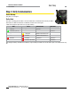
Step 2: Apply Power
1. Apply power to the Gateway by connecting the 10-30V dc cable as shown in the wiring diagram.
The Gateway begins in *RUN mode, displays the current network ID (NID), then identifies itself as a Gateway.
2. Apply power to the Node by connecting the 10-30V dc cable or the DX81 Battery Supply Module as shown.
The Node starts in *RUN mode, displays the current network ID, then identifies itself as a Node and lists the device ID. Once running,
the Node begins displays its I/O points.
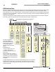
Wire Color 10 to 30V dc Powered
Node
Battery Powered Node
1 Brown +10 to 30V dc Input
2 White
3 Blue dc common (GND) dc common (GND)
4 Black
5 Gray 3.6 to 5.5V dc
For FlexPower devices, do not apply more than 5.5V dc to the gray wire.
RS-485 RS-232
Wire Color 10 to 30V dc Gateway,
GatewayPro, DX85*
FlexPower Gateway** GatewayPro, DX83
Ethernet Bridge*
FlexPower Gateway**
1 Brown +10 to 30V dc Input +10 to 30V dc Input +10 to 30V dc Input +10 to 30V dc Input
2 White RS-485 / D1 / B / + RS-485 / D1 / B / + RS-232 Tx RS-232 Tx
3 Blue dc common (GND) dc common (GND) dc common (GND) dc common (GND)
4 Black RS-485 / D0 / A / − RS-485 / D0 / A / − RS-232 Rx RS-232 Rx
5 Gray Comms grnd 3.6 to 5.5V dc Comms grnd 3.6 to 5.5V dc
* Connecting dc power to the communication pins will cause permanent damage.
** For FlexPower devices, do not apply more than 5.5V dc to the gray wire.
Step 3: Binding the Gateway and Nodes
Binding Nodes to their Gateway ensures the Nodes only exchange data with the Gateway they are bound to. The Gateway automatically
generates a unique extended addressing, or binding, code when the Gateway enters binding mode. This code is then transmitted to all radios
within range that are also in binding mode. After a Node is bound, the Node accepts data only from the Gateway to which it is bound. The
extended addressing (binding) code defines the network, and all radios within a network must use the same code.
After binding your Nodes to the Gateway, make note of the binding code displayed under the *DVCFG menu, XADR submenu on the LCD.
Knowing the binding code prevents having to re-bind all Nodes if your Gateway is ever replaced.
To automatically bind the Gateway and its Node(s), follow these steps:
On the Gateway
Step 1. Disconnect the Gateway from its power source.
Step 2. Remove the Gateway’s top cover.
Step 3. Move DIP switch 1 to the ON position to activate Extended Addressing Mode.
Step 4. Apply power to the Gateway. The LCD shows POWER, then *RUN.
Step 5.