
User Manual


Parameters
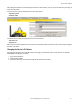
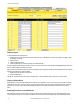
The following parameters are set on the Configure Points screen.
Change If you leave any Web Configurator screen with-
out clicking the Change button to submit the
changes to the Ethernet Bridge or Gateway-
Pro, all changes are lost.
Delta The delta parameter defines the change re-
quired between sample points of an analog in-
put before the analog input reports a new val-
ue. To turn off this option, set the Delta value
to 0.
Default
Output
Condi-
tion
Flags
The default output conditions are a set of
checkboxes to establish device-based parame-
ters and apply to all outputs on this device. Af-
ter making changes to the flags, click the Send
Flags button to submit the changes to the de-
vice.
Auto-Recover. Selecting the Auto-Recover
option forces the Gateway to attempt to re-es-
tablish communications with out-of-sync nodes
after a polling error condition is indicated. The
Gateway polls the failing device and must suc-
cessfully communicate with the failing node
Re-Link Count times before the error condition
is erased. This parameter is only used on the
Gateway. Without the auto-recover feature se-
lected, the user must manually reset error con-
ditions or the host system must reset the error
condition.
Gateway Link Failure. The Gateway detected
a communication problem with a Node. All
linked outputs of the failing device are set to
the default states.
Host Link Failure. A Modbus timeout forces
all device outputs to the default states. This
parameter applies to every device that sets
this flag.
Node Link Failure. A Node detected an RF
link problem and set its own outputs to the de-
fault states.
Out of Sync. When an out-of-sync condition is
detected, all Node outputs are set to the de-
fault value. This parameter applies only to the
Nodes.
Power Up. All device outputs are set to the de-
fault value on initial power-up.
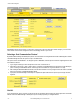
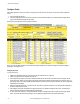
Get Info The Get Info button retrieves factory informa-
tion for the selected device, such as the model
number, serial number, and production date.
Prev
and
Next
If there are more than 16 devices or rules/maps,
use the Prev and Next buttons to display the next
screen of information.
Re-
fresh
Click the Refresh button to refresh the screen im-
age. This updates any information on the screen
that may have changed on the device.
Report
Inter-
val/
Rate
The report rate defines how often the Node com-
municates the I/O status to the Gateway. Change
of state reporting sets the system to report only
when the value crosses the threshold setting. For
FlexPower™ applications, setting the report rate
to a slower rate extends the battery life.
I/O Status
Re-
link
Count
The re-link count is the number of completed poll-
ing messages the Gateway receives from a Node
before a lost RF link is considered re-established
and normal operation resumes.
Reset The Reset button resets any error conditions dis-
played. Until the error message is reset, the de-
vice will not start any additional operations.
Sam-
ple In-
terval/
Rate
The sample interval, or rate, defines how often
the SureCross device samples the input. For bat-
tery-powered applications, setting a slower rate
extends the battery life.
SureCross Web Configurator
10 www.bannerengineering.com - tel: 763-544-3164 rev. -