
User Manual
3
5
1
2
4
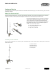
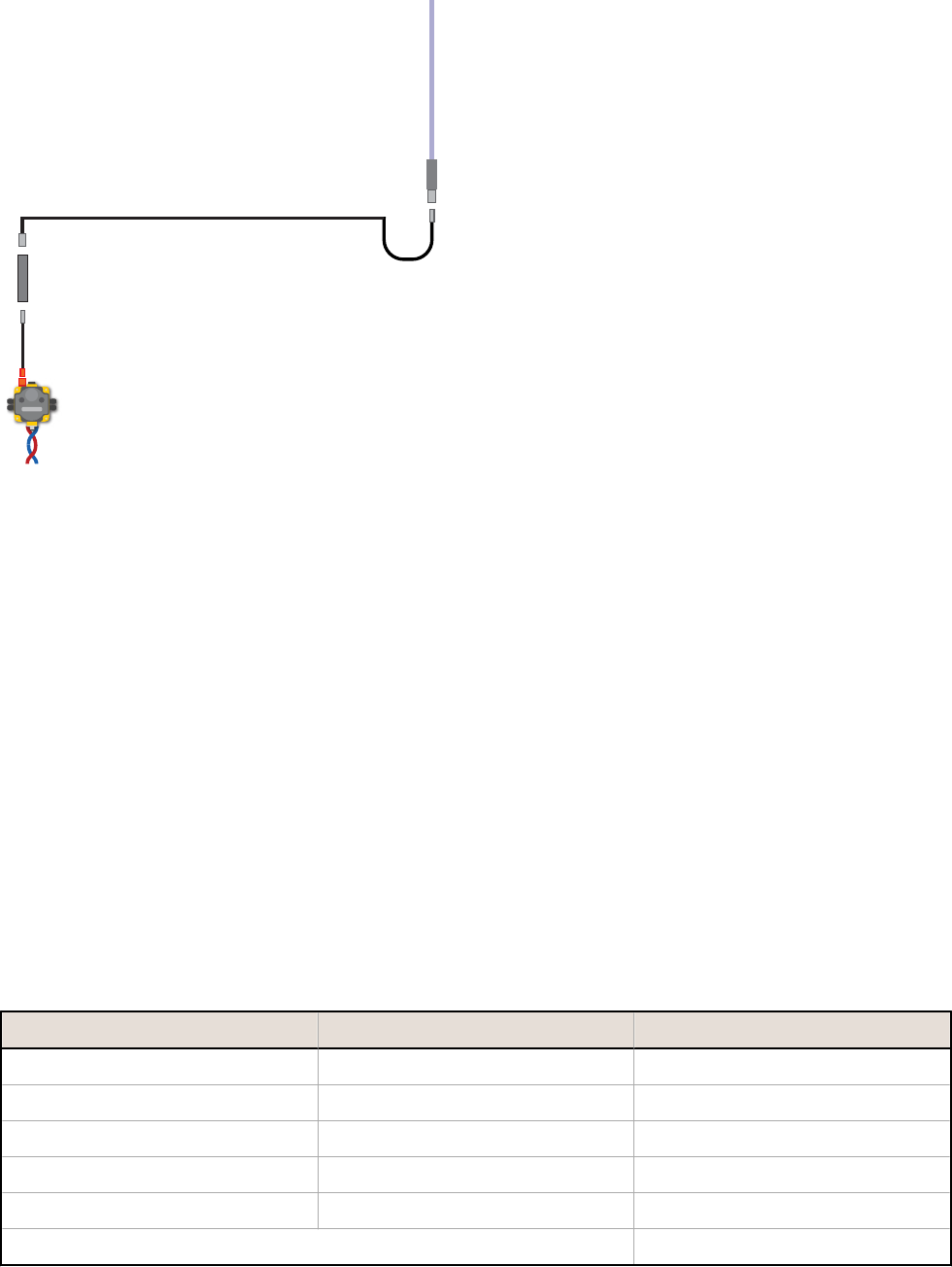
1. RP-SMA connection (–0.5 dB)
2. N-type male connection
3. Surge suppressor (N-type female to N-type male)
(–1.0 dB)
4. N-type male connection (cable) to N-type female
(antenna) (–0.5 dB)
5. Omni-directional antenna (6 dBd/8.15 dBi) *
Losses:
–0.5 dB per connection
–1.0 dB per surge suppressor
–3.9 per 100 feet of cable for LMR400 coax
Example Calculations - Free Space Loss
In addition to losses from cabling, connectors, and surge suppressors, radio signals also experience loss when traveling
through the air. The equations for free space loss are:
FSL
900MHz
= 31.5 + 20 Log d (where d is in meters)
FSL
2.4GHz
= 40 + 20 Log d (where d is in meters)
For a 900 MHz radio system transmitting three miles, the free space loss is:
FSL
900MHz
= 31.5 + 20 Log (3 × 5280/3.28)
FSL
900MHz
= 31.5 + 20 Log (4829.27)
FSL
900MHz
= 31.5 + 73.68 = 105.18 dB
Because this is a loss calculation, free space loss is a negative number.
Example Calculations - Receiver System
To calculate the link loss of the receiver system shown below, include the losses from each connector pair, the surge
suppressor, and the cable.
Device Estimated Gain or Loss
Radio's Power Output DX70 or DX80 radio N/A
Gains (+) or Losses (–) Connector pairs –1.0 dB
Surge suppressor –1.0 dB
Cable (50 ft length) –1.95 dB
Yagi antenna* +8.15 dBi
Effective gain of receiving antenna system 4.2 dBm
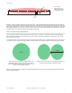
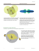
Antenna Basics
6 www.bannerengineering.com - tel: 763-544-3164 P/N 132113 Rev. H