Host Controller Systems Instruction Manual Original Instructions 132114 Rev.
Host Controller Systems Contents 1 Host Controller Systems ................................................................................................. 3 2 SureCross® DX80 Modbus Register Definitions ............................................................... 4 2.1 Modbus Holding Registers .......................................................................................................... 4 2.2 Alternative Modbus Register Organization ........................................................
1 Host Controller Systems The Host Controller Systems reference guide contains information about using Modbus RTU, Modbus/TCP, and EtherNet/IP commands with the SureCross DX80 family of products. This guide includes register maps, control codes, error message handling, supported function codes, and some sample commands to perform specific tasks. This guide also lists control codes and sample commands for configuring I/O parameters by writing to Modbus registers.
Host Controller Systems 2 SureCross® DX80 Modbus Register Definitions Modbus distinguishes between inputs and outputs and between bit-addressable and word addressable data items. For more information, please refer to www.modbus.org. A less documented but commonly used method to separate the data types is using a mapped address structure. Reference Description 0xxxx Read/Write Discrete Output. Drives output data to a discrete output point. 1xxxx Read Discrete Inputs.
Host Controller Systems 2.2 Alternative Modbus Register Organization The SureCross DX80 Alternative Modbus Register Organization registers are used for reordering data registers to allow host systems to efficiently access all inputs or outputs using a single Modbus command. The register groups include the input/output registers, bit-packed registers, and analog registers. This feature is only available with the Performance models using version 3 or newer of the LCD firmware code.
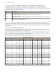
Host Controller Systems Bit-Packed Device Status R egisters Bit Position Register Address 15 14 13 12 11 10 9 8 7 6 6601 Node 15 Node 14 Node 13 Node 12 Node 11 Node 10 Node 9 Node 8 Node 7 Node 6 Node 5 5 Node 4 4 Node 3 3 Node 2 2 Node 1 1 Gateway 0 6602 Node 31 Node 30 Node 29 Node 28 Node 27 Node 26 Node 25 Node 24 Node 23 Node 22 Node 21 Node 20 Node 19 Node 18 Node 17 Node 16 6603 Node 47 Node 46 Node 45 Node 44 Node 43 Node 42 Node 41 Node 4
Host Controller Systems In this format, users can read a 16-bit holding register for all devices or write to a register for all devices using one Modbus message. Using these registers is the most efficient way to read all status registers, read all analog inputs, or write all analog outputs. The following registers contain analog I/O values for the Gateway and all Nodes. Values are stored first for the Gateway, then for each Node in order of Node address.
Host Controller Systems 2.4 Modbus RTU and Modbus/TCP Register Map Modbus/TCP and Modbus RTU provide device control and monitoring using holding registers in the 40000 register block. Each wireless device in the system is allocated 16 holding registers. The Gateway uses the first 16 registers followed by each Node in the network, based on the Node address. For Node 5, the starting Modbus registers are 1 + (Node# × 16) = 1 + (5 × 16) = 81, the ending register is 97.
Host Controller Systems Registers Device and Input Connections Register Device and Input Connections Register Device and Input Connections 15 Gateway I/O 15 31 Node 01 I/O 15 767 Node 47 I/O 15 16 Gateway I/O 16 32 Node 01 I/O 16 768 Node 47 I/O 16 9
Host Controller Systems 3 Web-based Configuration The SureCross wireless systems are configured using an Ethernet network connection and a common Web page browser. An Ethernet connection can be established from a GatewayPro or from a DX83 Ethernet Bridge serially connected to the Gateway. The Ethernet Bridge and GatewayPro each ship with an Ethernet crossover cable. One end of the cable is a RJ45 connector and the other end is an industrial Ethernet connector.
Host Controller Systems 3 Example Layout #3 This example system layout may also be configured using the web pages. Instead of using a GatewayPro to connect to the host system, a Gateway and Ethernet Bridge is used to achieve the same function. In this configuration, the Gateway is Modbus Slave 1. Host 1. Ethernet crossover cable using the Modbus/TCP or EtherNet/IP communication protocol 1 2. Power connection 2 3. DX83 Ethernet Bridge 4. Splitter cable CSRB-M1250M125.47M125.
Host Controller Systems 3. Enter system as the user name and admin as the password. After making your changes and saving the file, close the browser to log out of the configuration system. 3.2 Saving the System Configuration Save the system configuration by going to the System > Setup > Config File page. • To write the changes to the factory default XML file (BootConfig.xml), click the Save button. • To save the configuration changes under a different file name, enter the new XML file name, including the .
Host Controller Systems To use EtherNet/IP, the GatewayPro or DX83 Ethernet Bridge interface requires the user to enable the EtherNet/IP interface, define the EtherNet/IP registers, and save the system configuration using the System > Setup > Config File page. 3.3.1 Defining EtherNet/IP Registers to Send to the Buffer Define the registers sent to the EtherNet/IP interface buffers. On the System > Data > Local Registers tabs, select the EtherNet/IP checkbox for every register to be visible by Ethernet/IP.
Host Controller Systems The following tables show how the selecting inputs and outputs using the EIP checkbox maps device registers to the EIP buffer inputs and outputs.
Host Controller Systems 3.3.2 EtherNet/IP™ Registers 3.3.2 EtherNet/IP on ControlLogix PLC Register Map The DX80 wireless system is controlled by a ControlLogix PLC using EtherNet/IP through assembly objects and the Common Industrial Protocol (CIP). Add the SureCross Gateway to the ControlLogix PLC as a “Generic Ethernet Module.” There is one input assembly object for all DX80 input points and one output assembly object for all DX80 output points.
Host Controller Systems Output Assembly Object, DX80 Outputs, Instance 112 (0x70). Words are not allocated for any specific unit but are used, in device order, for each of the device output registers selected using the EIP checkbox. For proper EtherNet/IP communication, the minimum requested packet interval should be 150 milliseconds or higher.
4 Message Registers (I/O 7 and 8) Informational messages are warning or error conditions that include a message code and data field. The type of warning or error condition is encoded in the message code while the data field contains additional information for some message codes. Each DX80 model reserves four registers (defined I/O points) to provide information or control an operation. The reserved registers (I/O points) are 7, 8, 15, and 16.
Host Controller Systems Device Register 8 (Hex) Message Code [15:8] Data Field Description [7:0] 35 01 Radio Device (polling/heartbeat) Timeout. (Decimal value 13569.) A Node is determined to be out of the wireless network based on the parameters defined for polling or heartbeat. See the documentation in the UCT for polling or heartbeat parameters and the timeout operation. When the least significant bit is on (1), an error condition exists. • Run site survey to determine the quality of the RF link.
5 Control Registers (I/O 15) Use control messages to start device-level actions. Each DX80 device allocates 16 registers, with registers one through six reserved for inputs and nine through 14 reserved for outputs. Registers 7, 8, 15, and 16 are reserved for warnings, error messages, and control operations. The control messages use the device’s register 15. Some control messages are device specific, depending on the action required.
Host Controller Systems I/O 15 Control Messages Control Code in Hex (Dec) Data Field in Control Code Hex (Dec) and Data Field in Decimal Restrictions Description 0x11 (17) Bit Mask, see description 4352 0 = all bits off Gateway Link failure. Set the outputs to default states based on Bit Mask. Bit0 in the data field = I/O 9, bit1 = I/O 10, etc. The Gateway Link Failure flag must be set to enable this feature. 0x12 (18) 00 4608 Host Communication Timeout.
Host Controller Systems Reg 31 0x13 (19) 0x3F The full command, both bytes together into a word, in decimal would be 4864 + 63 = 4927 21
Host Controller Systems 6 Extended Control Registers (I/O 15 and 16) Use extended control messages to configure I/O parameters. Extended control messages allow custom configuration of I/O parameters, such as sample rate, threshold, and hysteresis, in a DX80 device. The I/O parameters are set using a host interface. The extended control message has three parts contained in registers of the Node to be updated. • • • Register 15 contains the extended control code and parameter number.
Host Controller Systems Extended Control Code (Dec) Description Extended Control Code (Dec) Description Extended Control Code (Dec) Description 0x89 (137) Write I/O 9 0xA9 (169) Read I/O 9 0xAF (175) Reserved 0x8A (138) Write I/O 10 0xAA (170) Read I/O 10 0xB0 (176) Reserved 0x8B (139) Write I/O 11 0xAB (171) Read I/O 11 0x8C (140) Write I/O 12 0xAC (172) Read I/O 12 0x8D (141) Write I/O 13 0xAD (173) Read I/O 13 0x8E (142) Write I/O 14 0xAE (174) Read I/O 14 6.
Host Controller Systems Low Pass Filter. This parameter defines the operation digital filters for standard analog inputs. Setting parameter bit 7 enables a median filter. Parameter bits [2:0] define the output filtering magnitude. (Parameter number 0x12). Power Supply # (bits 7:0). Turns on a local power supply to supply power to an external device. A parameter value of 0 indicates no power supply. A parameter value of 1, 2, 3, or 4 enables that particular internal supply connection.
Host Controller Systems Warm-up Time (bits 7:0). Values 01 through 127 set the number of 62.5 millisecond increments. Values 129 through 255 set the number of 250 microsecond increments, with 129 representing 250 microseconds, 130 representing two 250 microsecond increments (500 microseconds, and 255 representing 127 250 microsecond increments (or 31 milliseconds).
Host Controller Systems to 150 will detect only trucks of a specific size. Magnetic field fluctuations vary based on the amount of ferrous metal present and the distance from the sensor. If the threshold parameter is 0, there is no threshold and the analog input will report based on the delta rate. Value range: 0 (disable, default) through 65535 (two-byte value). (Threshold parameter number 0x08; Hysteresis parameter number 0x09). 6.2.
Host Controller Systems Type # Hex Dec 0x47 71 0x48 Description Type # Hex Dec 10 Ohm RTD (3-wire) IN 1 0xC5 197 72 10 Ohm RTD (3-wire) IN 2 0xC6 0x49 73 10 Ohm RTD (3-wire) IN 3 0x4A 74 0x40 Description Type # Description Hex Dec Thermocouple E1 0xD1 209 Thermocouple N1 198 Thermocouple E2 0xD2 210 Thermocouple N2 0xC7 199 Thermocouple E3 0xD3 211 Thermocouple N3 10 Ohm RTD (3-wire) IN 4 0x53 83 Thermocouple E4 0x57 87 Thermocouple N4 64 100 Ohm RTD (3-wire)
Host Controller Systems 6.2.
Host Controller Systems Units 6 Description Definition Temp °C Celsius, high resolution. Analog input for temperature devices such as thermocouples, RTD, and thermistors. In high resolution mode, temperature = (Modbus register value) ÷ 20. LCD: 0000.0C 7 Temp °F Fahrenheit, high resolution. Analog input for temperature devices such as thermocouples, RTD, and thermistors. In high resolution mode, temperature = (Modbus register value) ÷ 20. LCD: 0000.0F 8 Temp °C (Low Res) Celsuis, low resolution.
Host Controller Systems Units Description Definition 5 Signed Analog, 0 to 10V For a signed value, such as temperature, that is to be converted to a voltage out value. Use null to set the start point and span to define the range. The null value is the starting temperature to be associated with 0V. The span is the entire temperature range that is to be associated with 0 to 10V. LCD: 0.00V–10.
7 Host Controller Configuration Examples The following are some specific examples of using registers to clear an error condition, change device I/O parameters, and initiate a Site Survey. 7.1 Clearing Error Conditions Using Register Commands All non-zero messages must be cleared by the user from either the Gateway or the host system. The Gateway stores only the highest priority message in the register. A 0x00 message is not saved unless there is a 0x00 in the I/O point register.
Host Controller Systems There are 16 Modbus holding registers for each SureCross device. To calculate the registers for other Nodes, use this equation: Register number = I/O# + (Node # × 16). For example, the Gateway is always device 0 (or Node 0), so the Gateway’s holding registers are registers 1 through 16. The registers for Node 1 are 17 through 32 and the registers for Node 2 are 33 through 48.
Host Controller Systems 7.4 Example Command Modbus Register I/O 15 32 02 When Site Survey runs, the accumulated results are stored in the Gateway’s I/O 7 and I/O 8 holding registers. The LEDs on the both the Gateway and the Node’s front panel display the signal strength for the wireless RF link.
Host Controller Systems 8 Host Controller Software Configuration The following screenshots are configuration examples for specific software that may be used on a host system. 8 SLC 5 and ControlLogix Configuration Figure 1. SLC 5 Set-up MSG. In the example screen shown, a counter is set up to activate the MSG Read or MSG Write blocks every one second. Also two write and two read MSG blocks are shown. Each MSG block can only handle up to 103 words.
Host Controller Systems Figure 2. SLC 5 – MSG Read Instruction. The SLC 5 MSG read instruction with multi-hop enabled is shown. Click on the MultiHop tab and enter in the IP address of the DX80 Device (factory default 192.168.0.
Host Controller Systems Figure 3. SLC 5 – MSG Write Setup. The SLC 5 MSG write setup instruction with multi-hop enabled is shown. Click on the ‘MultiHop’ tab and enter in the IP address of the DX80 Device (factory default 192.168.0.1) 8 RSLogix 5000 Configuration To create an implicit Class 1 configuration to the DX80 using Ethernet/IP when using a ControlLogix family PLC, configure the DX80 as a “Generic Ethernet Module” under the ENET_MODULE.
Host Controller Systems Figure 5. Requested Packet Interval. Verify the Requested Packet Figure 4. Configure Banner Module Properties Interval is at least 150 milliseconds.
Host Controller Systems Figure 6. Banner DX80 inputs from wireless devices Figure 7.
9 Troubleshooting The following troubleshooting tips include some basic instructions for common problems. 9.1 Host Systems Problem Solution No communication with the Gateway when using RS-485 The default communications settings for the RS-485 port are: 1 start bit, 8 data bits, no parity, 1 stop bit, and 19.2k baud. The DX80 Gateway uses Modbus RTU protocol for all communications. Supported Modbus function codes are 3, 6, and 16. Verify the DX80 model supports RS-485 serial communications.
Host Controller Systems Device Register 8 (Hex) Message Code Data Field [15:8] Description [7:0] 35 01 Radio Device (polling/heartbeat) Timeout. (Decimal value 13569.) A Node is determined to be out of the wireless network based on the parameters defined for polling or heartbeat. See the documentation in the UCT for polling or heartbeat parameters and the timeout operation. When the least significant bit is on (1), an error condition exists. • Run site survey to determine the quality of the RF link.
Host Controller Systems Host System Node 1 Gateway Node 2 9.5 Serial Communication Configuration for DX83s The DX83 Ethernet Bridge uses jumpers to select between RS-485 and RS-232 communications. Install the four jumpers across the two top rows of pins for RS-485 and across the bottom two rows of pins for RS-232. Communication pins 9.
Host Controller Systems Initialization Pins To restore these settings, leave the device powered up and running and follow these steps: 1. 2. 3. 4. 5. Open the DX80 GatewayPro or DX83 Ethernet Bridge housing to access the board Install the initialization (init) jumper on the pins shown Wait 60 seconds Remove the jumper Cycle power to the device Using the configuration Web page, verify the parameters have returned to the factory defaults listed in the table. 9.
Index C control codes extended 22 control messages extended 22, 23, 25, 26, 28, 29 ControlLogix 34, 36 D default value 23, 25, 26, 28, 29 delta 23, 25, 26, 28, 29 duty cycle 23, 25, 26, 28, 29 E error host communication 39 no Web page access 40 unknown IP address 40 error code RF device time-out 17, 39 extended control codes 22, 23, 25, 26, 28, 29 F factory default settings 41 H host communication error 39 hysteresis 23, 25, 26, 28, 29 I invert flag 23, 25, 26, 28, 29 M Modbus time-out error code 17,