
Owner manual

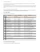

Warm-up Time (bits 7:0). Values 01 through 127 set the number of 62.5 millisecond increments. Values 129 through
255 set the number of 250 microsecond increments, with 129 representing 250 microseconds, 130 representing two 250
microsecond increments (500 microseconds, and 255 representing 127 250 microsecond increments (or 31 milliseconds).
When the device supplies power to external sensors, this parameter defines how long power is applied before the input
point is examined for changes. Value range: 00 (off, default) through 255. (Parameter number 0x05).
Internal Output Mapping. Reserved. Do not use. (Parameter number 0x1A).
Miscellaneous. Reserved. (Parameter number 0x17).
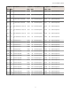
6.2 M-GAGE Parameters
M-GAGE Baseline Threshold/Filter. Under normal conditions, the ambient magnetic field fluctuates. When the magnetic
field readings drift below a threshold setting, the baseline or drift filter uses an algorithm to slowly match the radio
device’s baseline to the ambient magnetic field.
The baseline threshold/filter parameter sets a baseline threshold and filter activation time on M-GAGE devices. When M-
GAGE input readings are below the selected baseline threshold setting, the filter algorithm slowly lowers the magnetic
baseline reading to zero to remove small changes in the magnetic field over time. Setting options include the following
values: (Parameter number 0x13).
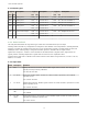
Filter Threshold 30, 2 hour Two hours after the M-GAGE reading of the ambient magnetic field (baseline) has dropped
below 30, the algorithm begins to slowly lower the magnetic baseline reading to zero.
Filter Threshold 30, 8 hour Eight hours after the M-GAGE reading of the ambient magnetic field (baseline) has dropped
below 30, the algorithm begins to slowly lower the magnetic baseline reading to zero.
M-GAGE Baseline Filter (unrestricted). An M-GAGE only parameter, the baseline filter parameter sets the coefficient
value of the baseline filter algorithm. (Parameter number 0x15).
M-GAGE Low Pass Filter. The filters T0 through T6 are parameter settings that define the degree of input digital signal
filtering for analog inputs. T0 is the least amount of filtering. T6 is the highest filter setting and has the least amount of
fluctuation between readings. (Parameter number 0x12).
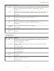
M-GAGE Report Rate (Inputs) . The report rate defines how often the Node communicates the I/O status to the
Gateway. Change of state reporting sets the system to report only when the value crosses the threshold setting. For
FlexPower
™
applications, setting the report rate to a slower rate extends the battery life. (Parameter number 0x04).
M-GAGE Sample High and M-GAGE Sample Low. For analog inputs, the sample high parameter defines the number of
consecutive samples the input signal must be above the threshold before a signal is considered active. Sample low defines
the number of consecutive samples the input signal must be below the threshold minus hysteresis before a signal is
considered deactivated. The sample high and sample low parameters are used to avoid unwanted input transitions.
This parameter can be applied to a discrete input or a analog input using the threshold parameter. (Sample high
parameter number 0x06, Sample low parameter number: 0x07).
M-GAGE Sample Rate. The sample interval, or rate, defines how often the SureCross device samples the input. For
battery-powered applications, setting a slower rate extends the battery life. (Parameter number 0x03).
M-GAGE Threshold and M-GAGE Hysteresis. Threshold and hysteresis work together to establish the ON and OFF
points of an analog input. The threshold defines a trigger point or reporting threshold (ON point) for a sensor input. Setting
a threshold establishes an ON point. Hysteresis defines how far below the threshold the analog input is required to be
before the input is considered OFF. A typical hysteresis value is 10% to 20% of the unit’s range.
The M-GAGE Node’s threshold and hysteresis ranges are 0 to 65,535. The factory default threshold setting is 100 and
default hysteresis is 30 (the sensor detects an OFF condition at threshold minus hysteresis, or 100 - 30 = 70). With the
default settings, once the magnetic field reading is above 100, an ON or “1” is stored in the lowest significant bit (LSB) in
the Modbus register. When the M-GAGE reading drops below the OFF point (threshold minus hysteresis), the LSB of the
Modbus register is set to “0.” To determine your threshold, take M-GAGE readings of the test objects at the distance they
are likely to be from the sensor. For example, if a car reads 100, a bicycle 15, and a truck reads 200, setting the threshold
Host Controller Systems
25