
Owner manual


7 Host Controller Configuration Examples
The following are some specific examples of using registers to clear an error condition, change device I/O parameters, and
initiate a Site Survey.
7.1 Clearing Error Conditions Using Register Commands
All non-zero messages must be cleared by the user from either the Gateway or the host system.
The Gateway stores only the highest priority message in the register. A 0x00 message is not saved unless there is a 0x00
in the I/O point register.
To disable all error reporting, send a value of 254 in the register for I/O point 8. To clear any I/O point 8 device message,
use the Gateway’s front panel menu system. A host connection can also choose to clear or disable I/O 8 registers. Nodes
ignore error messages.
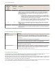
Control
Code
Data Field Restrictions Description
04 Node 01-47 Gateway only Reset error of Node # (defined by the data field). Control code
available only on the Gateway I/O 15 register. (This results in a 00
placed in the register I/O 8 of the appropriate Node)
05 Node 01-47 Gateway only Ignore error of Node # (defined by the data field). Control code
available only on the Gateway I/O 15 register.
06 Node 01-47 Gateway only Disable Error of Node # (defined by the data field). Control code
available only on the Gateway I/O 15 register (This results in a 254
placed in the register I/O 8 of the appropriate Node). Reset using
the Reset Error function (04)
7.2 Setting the Sample Rate
The sample rate establishes how often the SureCross device samples the sensors connected to it.
To set the sample rate to 900 seconds (15 minutes) on I/O point 1, Node #2, two register writes are required: register 47
and register 48 (Node 2’s register 15 and 16). Verify the transaction is completed by reading register 39 and verifying the
parameter control code and parameter number match the intended action.
1. Write the parameter control code (write I/O #1 = 129 = 0x81) and the parameter number (sample interval = 0x03)
into register 47. Concatenated, the register value is 0x8103.
2. Write the parameter data (900 seconds = 14400 62.5 millisecond intervals = 0x3840) into register 48.
Reg 48
0x38 0x40
Reg 47 0x81 0x03
3. Read register 39 to verify the message is completed.
Reg 39
0x81 0x03
7.3 Setting the Counter Preset using Register Commands
The event counter input is a 32-bit value that can be preset using the parameter control codes 143 (0x8F) and 144 (0x90).
Parameter control code 143 writes the lower half [15:0] of the counter and code 144 writes the upper half [31:16] of the
counter.
Select which counter to preset by defining the Counter Select Mask. The first bit position of the mask (bit 0, right justified)
selects the first counter and the second bit position selected the second counter. Set the Node’s register 16 to the high or
low data value. Read Node register 7 for the transfer acknowledgement. Write to Node register 16 before writing to Node
register 15.
31