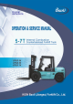
Original instructions
PREFACE Thank you for selecting BAOLI forklift truck! Your trust is a great honor to us! 5-7 Ton internal combustion counterbalanced forklift trucks which are drove by front axle adopt hydraulic transmission with advanced continuous speed control and integral drive axle with wheel reducer, so they have a lot of advantages such as good traction and travel performance, easy operation, wide visibility and reliable operation.
CONTENTS Ⅰ. About the forklift truck..........…….………………………................................1 1. External view and specification……………………………………………………1 2. Characteristic of forklift truck………………………………………………………3 Ⅱ. Safety usage, operation, maintenance and service of forklift truck……5 1. Handling a new forklift truck………………………………………………………5 2. Inspection before operation………………………………………………………5 3. Start and stop of the engine………………………………...................................6 4.
2.1 General description…………………………………………………………….39 2.2 Torque converter…………………………………………………………………41 2.3 Charging pump……………………………………………………………………42 2.4 Hydraulic clutch…………………………………………………………………..43 2.5 Control valve and inching valve…………………………………………………43 2.6 Hydraulic circulation system…………………………………………………….45 2.7 Principle……………………………………………………………………………46 2.8 Caution when the trouble occurs………………………………………………46 2.9 Trouble shooting…………………………………………………………………47 3. Front axle……………………………………………………………………………50 3.
6.3 Control valve…………………………………………………………………….76 6.4 Control valve operation………………………………………………………….77 6.5 Main safety valve operation……………………………………………………..79 6.6 Tilt lock valve operation…………………………………………………………80 6.7 Hydraulic circulation system (Main circuit)……………………………………..81 6.8 Troubleshooting………………………………………………………………….82 6.9 Maintenance……………………………………………………………………...83 7. Lift Cylinder & tilt Cylinder……………………………………………………….84 7.1 Lift cylinder……………………………………………………………………….84 7.
Ⅰ. About forklift truck 1.
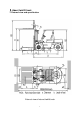
Main specification Model CPCD50 General Power type CPCD60 CPCD70 Diesel Rated capacity kg Load center 5000 6000 mm 500 3000 7000 Lift height H mm Free lift height H4 mm L × W×T mm 1200×150×55 1200×150×60 1200×150×65 mm 300/1700 α/β deg 6/12 X mm 622 627 632 Length to fork face L1 mm 3542 3547 3622 Overall width B1 mm 1995 Mast lowered height H1 mm 2500 Mast extended height H3 mm 4429 Overhead guard height H2 mm 2420 R mm Fork size Fork outside spread
2. Characteristic of forklift truck The forklift truck has advantages as follows: 1. The hydraulic steering device makes steering flexible and the double ladder like steering bridge makes the turning radius minor. 2. The braking system employs oil brake, makes it possible to manipulate conveniently and brake reliably. 3. Employed wide-vision extension type mast, the truck is high intensity. 4.
Main parts of forklift truck No. Name Contents 1 Power system 2 Transmission 3 Drive axle 4 Brake system 5 Steering system 6 Hydraulic system 7 Electric system 8 Load system engine mounting, system of fuel, exhaust and coolant etc. torque converter, transmission, transmission shaft, etc. housing, half shaft, differential, wheel reducer, brake, front wheel etc. wheel brake and parking brake steering wheel, cycloid gear type powered steering unit etc.
Ⅱ. Safety usage, operation, maintenance and service of forklift truck It is important for drivers and managers to remember the principle of “first safety” and ensure the safety operation as the description of Operation & Service Manual. Please read this manual thoroughly. This will give you a complete understanding of Baoli forklift truck and you will operate them correctly and safely. 1.
(5) Check hydraulic oil and brake fluid for leakage. Check if any leak or damage found on the oil pipes, water hoses, vent-pipes and the piping joints, pumps and valves etc. (6) Check for all the terminals and plugs in normal state. Check the meters, lamps, switches and electric circuit if they are running properly. (7) Check every pedal for free stroke and the levers for looseness and smooth operation.
steering operation for its flexibility, tyre pressure for its conformance to the standard. If there is no trouble, operation may be allowed. (2) Stop the engine First set the engine on idle running for five minutes, so as to cool the engine gradually, and then turn off the ignition switch, so the engine is stopped to work. Notice: .While the engine running, does not turn the start switch to “START” position, or it will damage the starting motor.
have their appointed sling position. The above-mentioned data is only for a reference, which may be adjusted because of configuration or technology optimization. (2) Load and unload the forklift truck (a) Use the plate with enough length, width and strength. (b) Pull the parking brake and use jacks to stop the wheel. (c) Fasten the plate on the center of the cabin, there must be no grease on the plate. (d) The left and right height of the plate must be equal to make the loading and unloading smooth.
(1) Safe parking (a) Park your forklift truck on a level ground preferably in a wide area. If parking on a slope is unavoidable, pull the parking brake device and block the wheels to prevent accidental roll. The forklift truck is forbidden parking on a steep slope. (b) Park your forklift truck in the area where designated or traffic conditions permit. If necessary, put a signpost or signal lights around the truck. (c) Park your forklift truck on the solid ground.
pipes. (d) Remove the key and keep it in a secure place. ·Long time storage Perform the following service and checks in addition to the “Daily storage” service: (a) Taking the rainy season into consideration, park the truck at a higher and hard ground. (b) Apply antirust oil to the exposed parts such as piston rods and shafts which tends to rust. (c) Cover components which may be caught with humidity. (d) The truck should be operated at least once a week.
operator shall be permitted to operate and service the truck. (2) Wear the safety guards, such as clothing, shoes, helmet and gloves while operating the truck. (3) When operating the truck, observe and follow all nameplates stuck on the truck. The nameplates must be replaced if lost or damaged. (4) Daily maintenance should be done before or after using the truck. Anytime you find that the truck is not functioning normally, operation of the truck should be halted and check or repair at once.
descending of the goods. When the goods are lifted or descended, the initial speed shouldn’t be too fast in either case. (14) When tilting the mast forward or backward to the limit or lifting the fork to the maximum height, return the directional lever to neutral. (15) The starting, turning, driving, braking and stopping of the truck should be done smoothly. When turning on the humid or slippery road, the truck should be decelerated.
200mm-300mm from the floor. (25) When handling bulky loads which block your view, operate the forklift truck in reverse or have a guide. (26) While mast’s lifting and lowering, anyone is absolutely prohibited from standing under the lift bracket or being lifted with forks. Never permit anyone to stand or walk under upraised forks. (27) When lifting the load, according to the weight of the load, accelerate properly and then pull the lifting lever.
(39) Before the truck decelerating and stopping, don’t change gear to reverse shift, so as to ensure the safe loading. (40) When the truck stops and the engine is on idle position, the mast must be tilted backward. You shouldn’t leave the truck with idling engine or hanged goods unattended. (41) When adding fuel, make the driver leave the truck and the engine flameout. Don’t ignite when checking the level of fuel tank. (42) Don’t open the radiator cap when the engine is very hot.
an elevation of 1000 meters and temperature between -20℃and 40℃, relative humidity is 95%. Careful operation must observe under other adverse circumstances. (53) Because of the danger for the people, the forklift is forbidden operating in airtight space, or you may be choked by the tail gas. The tail gas’s exhausting standard shouldn’t be lower than the no-load mechanical vehicle exhaust standard ruled by the nation that users are in.
7. Operation device and meter 1. 2. 3. 4. 5. 6. 7. 8. 9. 10. Inching pedal 11. Air filter indicator (option) Button for stopping engine Brake pedal Parking brake lever Hand wheel adjusting lever Shift lever Oil pressure indicator Fuel gauge Charge signal Neutral signal 12. 13. 14. 15. 16. 17. 18. 19. Coolant temp.
The function and use method of operation device and meter is listed as follows: No Name Function 1 Inching pedal Couple or uncouple the transmission. 2 Flameout pull button Stop the engine. 3 Brake pedal Brake the truck. 4 Parking brake lever Park the truck. 5 Hand wheel adjusting lever 6 Shift lever 7 Oil pressure indicator Adjust the angle of steering wheel. Change the travel direction. Indicate the pressure of engine oil. 8 Fuel gauge Indicate the fuel capacity.
8. Caution plate The caution plates attached on the vehicle indicates the operating method and instructions. Before driving it, please be sure to read them thoroughly. If the caution plate drops, stick it again. When maintaining, check if the caution plate is complete and the writing is legible, if necessary, please replace them. (1) Safety mark (People are forbidden to stand on or down the fork.
(4) Lubrication system (5) Capacity chart (6) Inspections before starting 19
(7) Adjust parking brake (8) Add hydraulic oil (9) Add fuel (10) Add antifreeze (11) Tyre safety decal (charging tyre) (12) Tyre pressure decal (charging tyre) 20
(13) Cautions for high voltage (14) Sling point indication (15) Sling decal (16) Forbid entering into the space behind the mast (17) Forbid conveying person 21
(18) Hand caution decal (19) Fan hurting hands (20) Hood crushing hands Energy accumulator decal Belt pulley thumb hand decal 22
Ⅲ. Periodic inspection and servicing During operating the forklift truck, it is necessary to operate carefully, service and maintain periodically to make the forklift truck keep in good condition. 1. General rules on inspection and maintenance (1) Only use genuine parts provided by our company. (2) Only use genuine or recommended oil when replacing or adding. (3) Clean oil fillers and grease fittings with a brush or waste cloth before adding oil or grease.
2. Essentials of servicing (1) Some critical components must be replaced according to demands periodically. Use genuine parts only. (2) Use the same model oil only when replacing or adding. (3) If any damage or fault is found, stop the truck and report the condition to the manager. Do not operate the truck until it has been repaired completely. Periodic service and maintenance must be done according to the following list after using the forklift truck. No. Item Contents Period (hrs.
3.
Lubrication diagram 26
5. Routine check before daily operation (1) Check the storage of fuel. (2) Check if any leak or damage found on the oil pipe, water hose, vent-pipe and hydraulic parts. (3) Check whether the hydraulic hose storage attain to the regular capacity, the oil level should be at the middle position between the upper and lower scale marks of oil level meter. (4) Check if fix or loose found on the wheel bolt and transmission bolt. (5) Check tires air pressure.
Ⅳ. Construction, principle, adjustment and maintenance of forklift truck In order to keep good condition of your truck, you must have an intimate understanding of the construction, principle, adjustment and maintenance of the forklift truck. When find damage or a fault at the truck, stop operating the truck and inform a professional serviceman. Use genuine parts of our company for replacement. 1. Power System 1.
1.2 Engine disposition The engine used for 5-7t forklift truck includes the import engine 6BG1 (ISUZU), the home engine 6102BG6 (Zhaoyang). Type Diesel engine Mitsubishi Zhaocai Weifang Cummins S6S-T 6102BG6 R4105G32 QSB4.5 82.3/2000 63.9/2300 81/2500 59/2400 82/2200 416/1600 285/1700 353/1600 270/1600 488/1500 6 6 6 4 4 mm 105×125 94×120 102×118 105×125 102×137 L 6.494 4.996 5.785 4.33 4.5 Engine model A-6BG1QC-02 kw/ Rated output / Speed rpm N.
Fig.1.2 A-6BG1QC diesel engine Main performance and disposition of A-6BG1QC Model A-6BG1QC Type 4-cycle,water-cooled,overhead valve No. of cylinder—bore×stroke 6-105mm×125mm Total displacement L Performance Compression ratio 6.494 17 Rated speed rpm 2000 Rated output kw 82.3 Max. torque Full-load fuel consumption No-load Min. speed N.m/rpm g/kwh 233 rpm 700 kg 450 Weight Dimension Injection start pressure Compress pressure 416/1400-1600 mm 1129.5×672.0×860.
1.3 Inspection and adjustment of engine In order to keep good condition of your truck, you must carry out periodic inspection and adjustment of power system. (1) Regularly clear the dust of air cleaner. (2) Regularly replace oil filter and fuel filter. (3) Check and apply the coolant periodically. (4) Periodic inspection of throttle valve and injection pump. (5) Check fan belt for tension and all fasteners. Note: Always check the exhaust gas of the engine during using the forklift truck.
1.4.2 Fuel sensor The function of the fuel sensor is to change the oil in the oil tank to the electric through the bobber up and down sport, in the end transfer to the fuel chart in the dashboard, let others to know the oil quantity directly. See Fig.1.4. (a) Once every 600 hours operation, it is required to replace the filter assembly.
1.4.3 Fuel filter The fuel filter was installed in the engine enters hose, used to filtrate the fuel supply to the engine. There also have other through valve inside of the filter, when the filter jammed, it also can supply the oil to the engine. See Fig.1.5. 1.5 Coolant system The coolant system composed with water pump, fan, radiator and the ancillary radiator, the water pump installed in the engine, the crank through the V-series tape to drive the water pump work. 1.
1.6.3 Replacement of oil filter (Fig.1.8) (1) Use the filter specially spanner disassemble and change. (2) Along with the around of the new oil filter seal o-ring, add little lube then install, when it contact the filter, screw 2/3 circle. Fig.1.8 Oil filter 1.6.4 Vice radiator (Fig.1.9) (1) Check the coolant in the vice radiator The ancillary radiator as Fig.1.8, when the antifreeze under the “LOW” scale, it means need to add coolant, add to the 2/3 scale of the up and down scale.
1.6.5 Adjust the fan belt If the fan belt is loose, tighten it. See Fig.1.10. Step: loosen the fixed bolt B and C of generator, move the generator out. Press the A section of belt with the force of 10kg strength, the flexible degree is about 10mm, then tighten the bolt B,C orderly. 1.6.6 Tighten the bolt of the engine cylinder end (1) Tighten the bolt with 68Nm twisting moment by the order of Fig 1.11. (2) Tighten the twisting moment to 93Nm, then tighten the bolt orderly.
Fig.1.13 Fig.1.14 The material adjustment see Table. Cylinder NO. I:inspiration valve 1 2 I E I △ △ △ 3 E I 4 E I △ △ 5 E I 6 E I E ※ ※ E: exhaust valve 1st cyl. in TDC ※ 6th cyl. in TDC ※ △ ※ ※ 1.6.8 Fuel injection ignition time affirmation (1) Affirm if the "assemble countermark" is in conformity with the place of injection pump flange. See Fig1.15. (2) Put the 1st cylinder to the TDC position, turn the crank shaft about 30° counterclockwise, See Fig1.16. Fig.1.15 Fig.1.
(3) Loosen the 1st cylinder injection pipe, dismantle the spring on drain valve bracket and drain valve, then install the drain valve bracket on injection pump. See Fig1.17. Fig.1.17 4) While charging pump transmit fuel, it turn the crank shaft clockwise , when the fuel lever of drain valve bracket up to the stop position, stop turning the crank shaft. Affirm the hand sign. See Fig 1.18. Fig.1.18 1.6.9 Fuel injection ignition time adjustment (1) Dismantle pipe installed on injection pump.
(1) Dismantle heat spark plug and fuel injection pipe. (2) Install manometer on the heat spark plug of 1st cylinder, the demarcate value of the manometer is 500N/ cm2. (3) Running the starting device by plenty battery, meter the pressure at this time. (4) Measure the other 5 cylinder by the same way, and measure 2 times, then figure out each average value; compression pressure: 304N/cm2 (limit value 255N/cm2) 1.6.11 Exhaust of injection pump ( Fig 1.20) (1) Loosen core vent of injection pump.
2. Drive unit Drive unit consists of torque converter and a hydraulic transmission. The structure of the hydraulic transmission refers to Fig.2.1, the structure of the torque converter refers to Fig.2.2. Main technical parameter Item Torque converter Type 3-element,1-stage,2-phase type Torque converter ratio 12.5″(Φ315) ratio 3.1 Pressure setting Charging Type pump Flow rate Transmission Mpa 0.5~0.7 Inner-mesh gear type L/min 40 (2000rpm, 2Mpa) Type Power-shift constant mesh Shift NO.
Fig.2.1 Torque converter transmission 1. Control valve 2. Charging pump 3. 9. Parking brake 17. Oil seal 10. Strainer 18. Ball bearing Ball bearing 11. Oil seal 19. Gear 4. Drive shaft 12. Gear 20. Reverse clutch pack 5. Ball bearing 13. Ball bearing 21. Forward clutch pack 6. Torque converter 14. Shaft 22. Input plate 7. Ball bearing 15. Bearing cover 23. Transmission output shaft 8. Gear 16.
2.2 Torque converter The torque converter consists of pump wheel installed on input shaft, a turbine wheel installed on output shaft and stator wheel fixed on torque converter body. The structure of the torque converter refers to Fig.2-2. Pump rotor is driven by elastic plate, the elastic plate is connected with flywheel, the pump rotor start turning while the engine is running. The liquid in pump rotor eject along blade lattice. The mechanical energy changes to kinetic energy.
Fig.2.2 Torque conv Fig 2.2 Torque converter 2.3 Charging pump Fig 2.3 shows the structure of charging pump. The charging pump consists of drive gear, driven gear, case and cover. They are fixed on the head of torque converter housing. The drive gear is driven by pump wheel, driven gear and drive gear, the charging pump feeds oil in the under part of transmission to each part of it. Fig.2.
2.4 Hydraulic clutch Fwd clutch see Fig 2.4, reverse clutch see Fig.2.5. There is a hydraulic clutch fixed on transmission, the drive gear on the side of clutch is engaged with the corresponding driven gear, the drive gear on the side of reverse clutch is engaged with the opposite gear. The clutch is consists of 6 clutch disks and 7 steel plates. They are installed alternately and assembled with piston.
Fig.2.4 Forward shift clutch Fig.2.5 Reverse shift clutch Fig.2.
2.6 Hydraulic circulation system (see Fig. 2.7) When the engine is started and the charging pump is put into operation, the torque converter fluid in the oil tank (transmission case) is forcibly sent to the control valve from the pump through the strainer. The fluid sent from the charging pump is divided to two directions in the torque converter case, one for torque converter and the other for transmission. Pressure of the fluid for clutch is adjusted to 1.2 to 1.5 MPa with the relief valve.
Fig. 2.7 Hydraulic circulation system 2.7 Principle The torque converter consists primarily of a pump wheel connected to the input shaft, a turbine wheel connected to the output shaft, and a stator wheel fixed to the housing. The transmission consists of charging pump, hydraulic clutch, the forward gear and reverse gear.
2.9 Trouble shooting (1) Insufficient power Parts Problem Possible cause and remedy A. Too low oil pressure 1. Lower oil level Check oil level and add oil. 2. Air entering in resulting from loose connectors. Torque converter Check connectors or oil pipes. Retighten each connectors or replace seals. 3. Blocked oil filter Check, clean or replace 4. Oil can not be pumped out. Check and replace. 5. Deformed spring of relief valve. 6.
(2) Too higher oil temperature Parts Problem Possible cause and remedy 1. Lower oil level Check oil level and add oil. 2. Blocked oil filter Check, clean or replace. 3. Fly wheel bump against other parts. Torque converter Check oil, if have dirt, replace it. Check connectors or oil pipes. 4. Air entering in resulting Retighten each connector or from loose connectors. replace seals. 5. Water mixed into oil Check and replace oil. 6. Low oil flow Check pipes and replace. 7.
(4) Too lower transmission efficiency Parts Torque Problem Possible cause and remedy 1. Elasticity plate is broken. Check turn noise and replace. 2. Lower oil amount. Check oil level and add oil. 3. Driving system of oil pump is ineffective. converter Check and replace. 4. Shaft is broken. Check and replace. 5. Too lower oil pressure. Check oil pump for suction pipe. 1. Lower oil amount. Check oil level and add oil. 2. Seal ring is worn. Check and replace. 3. Slipped clutch.
3. Front axle The main specifications of the front axle: Type Full-floating type, integral shaped Type Spiral bevel pinion type Main reduction gear Reduction ratio 4.75 Type Planetary gear type Final reduction gear Reduction ratio 4.25 Total reduction ratio 20.19 Main reduction gear Amount of oil 10 L Differential Final reduction gear Driving wheel 8 L (left and right) Tire 8.25-15-14PR Rim 6.50-15 Air pressure KPa 800 3.
gear. However, since the ring gear is fixed to the spindle, the pinion gears revolve around the sun gear while spinning themselves. The pinion gears are installed to the carrier which is fixed to the wheel hub, therefore, power of the drive shaft causes the wheel to turn. Fig. 3.1 Front axle 1. 2. 3. 4. 5. 6. Axle housing Haft shaft Wheel brake Brake drum Oil seal Taper roller bearing 7. 8. 9. 10. 11. 12. Hub Taper roller bearing Adjusting nut Lock nut Planet carrier Thrust cap 51 13. 14. 15. 16. 17.
Fig. 3.2 Reducer & differential 1. 2. 3. 4. 5. 6. 7. 8. 9. 10. Adjust nut Cap Lock plate Taper roller bearing Plain half Side gear Pinion gear Spiral bevel pinion Spider Thrust washer 11. 12. 13. 14. 15. 16. 17. 18. 19. 20. Flange half Side gear Thrust washer Roller bearing Carrier Lock nut Adjust bolt Drive pinion Taper roller bearing Bearing cage 52 21. 22. 23. 24. 25. 26. 27. 28. 29. 30.
Fig. 3.3 Final reduction gear 3.4 Troubleshooting Trouble Cause Loose bolt or broken gasket of differential carrier. Breather is clogged. Oil seal is worn or damaged. Gear is worn, damaged or broken. Bearing is worn, damaged or broken. Improper backlash. Loose spline fitness of side gear to propeller shaft. Insufficient gear oil. Oil leaks from differential carrier. Noisy differential. Correction Retighten or replace. Clean or replace. Replace. Replace. Replace. Adjust Replace parts. Add as necessary.
4. Brake system 4.1 General description The brake system consists of two wheel brakes installed on the front axle and parking brake on the propeller shaft. The wheel brake is vacuum servo type. 4.2 Power brake (see Fig.4.1) The wheel brake system consists of brake pedal, brake valve, power accumulator and brake.
Fig. 4.2 Position of brake pedal 4.2.2 Brake valve (Fig. 4.3) (1) Non-brake state Since the brake valve A port is open, the nozzle of the pump and powered steering is interlinked, the operation of steering is normal in the state of non-brake. When the brake pedal isn’t been pressed, the oil pressure in the chamber D won’t go up in that the port B is close. (2) Brake state A.
return spring 6 is compressed to the left. B. A port is closed owing to the shift of the part 7, and chamber D disconnects with the port of the return oil tank, and the chamber D connects with the port of pump in that the port B is closed. C. Now the valve sleeve 7 shifts to the left, the oil pressure of the pump port and the chamber D rises in that the C is compressed, in the meantime, the recoil piston 5 is pushed by higher oil pressure in the chamber D . D. When the max.
pressure alarm switch inside it. Preventive maintenance should be done by authorized serviceman. Failure to use will cause crack. Depressurization treatment should be done when the truck parking or preventive maintenance. The method to decrease the pressure: After the engine is flameout, press the brake pedal for 5 to 8 times, then the pressure of reservoir in brake system can be decreased. Fig. 4.3 Brake valve 1. 2. 3. 4. Plug One-way valve base One-way valve pin Piston guide base 5. 6. 7. 8.
4.3 Vacuum booster Using the vacuum booster with the power cylinder can make the forklift truck brake. Vacuum booster boosts brake fluid by the pressure difference between the vacuum pressure and the atmospheric pressure, higher oil pressure of the brake cylinder can reduce the intensity of the drivers and improve the brake security. 4.3.
control valve push rod 1 and piston 5 shift backward, the air valve 4 keeps away from the vacuum valve port. Thus the brake process ends. 4.3.2 Assembly of vacuum booster and master cylinder (1) Assemble the bolt of the vacuum booster and installation bracket on the truck frame, connect the adjusting fork on the end of the vacuum booster with the link lever of the brake pedal, tighten the nut with torque 12N.m-18N.m. (2) Connect the vacuum tube with the tube connector to offer air tightness.
Fig4.5 Outline of vacuum booster and master cylinder 1. Push rod, control valve 2. Filter cushion 3. Cone spring 4. Air valve 5. Piston, control valve 6. Cone spring 7. Control valve body 8. Case, rear film 9. Rear film 10. Feedback disk 11. Case, front film 12. Front film 13. Push rod, master cylinder 14. Return spring 15. Connector Fig. 4.
4.4 Parking brake The parking brake is of internal expansion and lining type, and built in the output shaft of the torque converter transmission. The operation of the parking brake is shown in Fig.4.7. When the forklift truck is parked on a slope with standard capacity, the hand operation force should below 300N. Adjust the pull force by diagrammatic direction. 4.5 Wheel brake (Fig. 4.
Fig. 4.8 Wheel brake 1. 2. 3. 4. 5. Primary brake shoe Return spring Dust ring Cup Piston 6. 7. 8. 9. 10. Pull rod Secondary brake shoe Return spring Fixed pin Spring 62 11. 12. 13. 14.
4.
5. Steering system 5.1 General description Steering system contains mainly a steering hand wheel, a steering column, a cardan joint, a powered steering unit, a steering axle and a steering cylinder. The steering shaft is connected with the steering unit and steering hand wheel by the joint. The steering column may be tilted properly forward or backward. Turn the hand wheel clockwise, the forklift truck will turn to the right, on the contrary, the truck will turn to the left.
5.2 Hand wheel Hand wheel is operated in normal way, that is to say, when turning the hand wheel right, the truck will turn right. When turning the hand wheel left, the truck will turn left. The rear wheels of the forklift truck are steering wheels, which make the tail section of the truck swing out when turning. The turning method can be mastered easily through practice. 5.
5.3.1 Steering unit assy Fig.5.2 Cycloid gear type powered steering unit 1. Spacing sleeve 6. Joint sleeve 2. Valve body 7. Rotor 3. Valve core 8. Stator 4. Interlock shaft 9. Valve sleeve 5.
5.3.2 Work principle Valve bore, valve sleeve, valve body in the redirector makes up of along valve, having an effect of controlling the direction of the oil flow. Rotor and stator makes up of cycloid mesh, having an effect of measure element when turning, to make sure that the oil quantity in oil crock and corner of steering wheel makes direct ratio; having an effect of hand moving oil pump when turning by manpower; and linkage shaft having an effect of transferring wrest rules.
5.3.3 Usage of the steering unit (1) Install the steering unit When installing the steering unit, it must ensure concentric with the connecting shaft, axial clearance can avoid propping by valve core, checking the hand wheel if it can return to the neutral position flexibly after installing. The allowable flow rate of the inlet oil pipe is 1-1.5m/s, the allowable flow rate of the outlet oil pipe is 4-5m/s. The experimental pressure of the high pressure tube must high than 1.
In order to keep the steering system in good working condition and avoid accidents, it is necessary to check the steering system regularly. The structure of steering unit is referred to Fig5.4. (1) Regularly check water, foreign matter and acid number of the working oil, if necessary, replace it with new oil. (2) When checking the steering system, don’t disassembly the steering unit readily, if the steering unit is in trouble, please ask professional service men to repair it.
If disassemble from the rear cover, before removing the valve core and valve sleeve, firstly get out valve ball, or the valve body will be damaged, be care not hurt the other surface of valve body. b. Order of assembly valve core - spring piece valve sleeve - shift arm- shim valve body - slip ring - block ring - front cover - steel ball screw cover - block plate interlock shaft - rotor - stator - spacing sleeve - back cover. Fig5.4 Structure of steering unit 5.3.
of the steering wheel with the parking detent, to measure the operation of steering, which must be under 150N. (5) Measure the pressure with pressure meter (15-20MPa), cutoff valve and soft tube in Fig. 5.5. Remove the split-flow valve to the line of the turning implement, engage a line with pressure meter on the side of diffluent valve, engage a line with breaking valve on the side of turning implement, then make the engine run at a slack speed.
5.3.6 Steering unit troubleshooting Problem Possible cause Remedy Oil leaks from the connection surface of valve body, stator and rear cap due to the dirty. Clean. The rubber ring is worn. Replace rubber ring. The washer of limit bolt is uneven. Grind or replace washer. Oil pump can’t supply insufficient fuel. Select appropriate oil pump or check the divider. Air mixed in steering system. Vent air and check oil pipes. Oil tank isn’t full. Add oil to specified level. Oil is too sticky.
5.4 Steering system troubleshooting 5.4.1 Inspection after reassembling the steering system (1) Check the force when turning the steering handwheel to right and left until it can’t be turned any more to see if they are identical each other and check the operation if the steering handwheel for smoothness during above operation. (2) Check the arrangement of the hydraulic pipeline and the turning direction for correctness.
5.5 Rear axle The rear axle is primarily composed of an axle body, right and left knuckles, tie rods, wheels, hubs and steering cylinder. The steering axle is of cranks and slider mechanism. The cylinder piston rod pushes the knuckle steering through tie rod, causing wheel’s deflection and truck’s steering. The steering axle is bolted to the rear frame by the buffer. (1) Rear axle body The rear axle body is of the steel plate weld construction type and has boss holes for knuckles at both ends.
(4) Rear wheel bearing pre-load adjustment a. As shown in Fig5.7, fill up the chamber formed by wheel hubs, wheel hub bearing and wheel hub covers with lubricating grease. Coat the lips of the oil seals with lubricating grease. b. Press the hub bearing into the hub and fit the hub on the knuckle shaft. c. Fit a flat washer and tighten a castle nut with torque of 206~235N.m and loosen it and then tighten it again with torque of 9.8N.m. d.
6. Hydraulic system Hydraulic Type oil pump Displacement Type Control valve Gear pump 32 ml/r 36 ml/r Two-pool type with relief valve, flow divider and tilt self-locking valve Setting 19 MPa pressure Dividing 12 MPa pressure Flow rate 25 L/min 6.1 General description The hydraulic system mainly consists of main pump, control valve, high & low pressure oil pipes and joints. The main pump is a gear type and installed on the side of the transmission.
Caution: Don’t adjust the pressure of the main relief valve at will. If the pressure is too high, the hydraulic system and hydraulic component may be damaged. When maintaining or using, if oil pressure isn’t the same as the standard value, on the basis of JB/TT3300 test way, the professional serviceman should adjust the pressure according to the following procedures: (a) Screw the plug screw off the inlet port of the control valve, install a 25MPa oil pressure gauge.
Fig.6.2 Middle position (2) Push slide valve (See Fig.6.3) At that time, the middle passage is off. The oil that is come from the oil enter will push out the one-way valve, and inflood cylinder port B. The oil that is expelled from the cylinder port A will pass the low-pressure passage and be back to fuel tank. The slide valve will replace to the middle position recur to the replacement spring. (3) Pull slide valve (See Fig.6.4) This moment, the middle position passage is off.
6.5 Main safety valve operation (1)The main safety valve must be installed between the cylinder HP port and LP passage. The oil that pass through the valve core will be acting on the different diameter surface A & B, so the core K of the one-way valve and the core D of the main safety valve will be firmly fall into the valve base. (See Fig.6.
6.6 Tilt lock valve operation Tilt lock valve is used for preventing the shaking of the mast (because the tilt cylinder maybe cause the inside negative pressure), at the same time, it can avoid the danger that the mast will be tilted due to the wrong operation (hit the tilt operation staff) when the engine is off. In traditional structure, even if the engine is off, the mast will be pitch if someone hit the tilt operation staff.
6.7 Hydraulic circulation system (Main circuit) The hydraulic system sketch sees Fig. 6.10. The hydraulic circulation system of the main circuit is complicated with the hydraulic for power steering. The hydraulic piping is of O-ring fitting type with excellent sealing performance, providing secure oil tightness.
the piston rod. When the lift lever is pushed, the circuit between the lower part of the lift cylinder piston and the oil tank is opened, and the piston begins to descend due to the weight of the piston rod, lift bracket, forks, etc. In this case, the oil returning to the control valve is regulated by the flow regulator. When the tilt lever is operated, the hydraulic oil from the main pump reaches one side of the piston to push it.
6.9 Maintenance 6.9.1 Detaching of multi-way valve Detach the valve from forklift and clean it. (1) Loose bolts and separate each part, please note that 1-way valve or spring on contact surface shall be kept well. (2) Loose the bolts at a side of slide valve end as well as at cover side, and then detach them together with valve leather, o-ring and sealing washer.
7. Lift cylinder & tilt cylinder Lift cylinder Tilt cylinder Type Single-action piston type, with cut-off valve Φ80mm Bore diameter Stroke 1495mm (Only for 3m lift height) Type Double-action piston type Φ115mm Bore diameter Stroke 227mm 7.1 Lift cylinder The two lift cylinders of single acting type are used and located behind each outer mast frame.
Note: Please pay more regard to safety when adjusting the lift cylinder. 1. Adjusting pacer 2. Dust ring 3. Yx ring 4. Cylinder cap 5. Bushing 6. O-seal ring 7. Cylinder body 8. Piston rod 9. O-ring, seal 10. Wear ring 11. Yx ring 12. Nut 13. Cotter pin 14. Lift chain 15. Chain wheel 16. Ball bearing 17. Spring 18. Cut-off valve 19. Upper beam Fig.7.
7.2 Flow regulator The flow regulator is located between the control valve and the high pressure ports of the two lift cylinders, near the left lift cylinder. The structure of the flow regulator valve is shown in Fig7.2. When the lift spool valve is placed in the “lift” position, the oil from the control valve flows through the oil chambers A and B, C, oil holes H, G, D, E, and the chamber I to the lift cylinder without any regulation.
7.3 Tilt cylinder Two tilt cylinders of double acting type are provided at each side of the frame. The front end of the piston rod is installed on the mast and the cylinder tail is on the frame with pins. The tilt cylinder assembly consists primarily of a cylinder body, cylinder cap, piston and piston rod. The structure of the tilt cylinder is shown as Fig7.3.
8. Lifting system 8.1 General description The lifting system is of two-stage, rolling telescopic mast type. The inner mast frames have J-shaped section. The outer mast frames have C-shaped section. The masts of forklift trucks all contain a free lift range. The structure of the mast sees Fig. 8.1. 8.2 Inner & outer mast The mast assembly is of the free lift range-contained two stage telescopic type consisting of the inner and outer mast, and is sustained by mast supports.
sustained by upper retaining rollers and lower side rollers. As we mentioned above, the mast assembly and lift brackets are designed with rigidity, stability and smooth operation in mind. Furthermore, the finger bar and lift brackets are made into one body construction using high tension steel to improve the durability. This meets the ISO Standards. The two forks installed on the finger bar are made of special alloy steel which has been subjected to heat treatment.
Fig8.2 Roller mounting 8.5 Adjustment of lifting system a. The clearance between the inner mast and the guide plate of the outer mast is 0.5-1.0mm, which is adjusted by the spacer of the guide plate. The clearance between the side roller and the channel beam is 0.3-0.8mm, which is adjusted by the axial bolt inner the roller. b.
(3) Install shims between the top of the piston rod of the cylinder which stop first and the upper beam of the inner mast. The thickness of the shim is 0.2mm or 0.5mm. (4) Adjust the tightness of lift chains. Fig8.3 Notice: Please pay more regard to safety when adjusting the lift cylinder at an elevated height. 8.6.2 Carriage adjustment (1) Park forklift on horizontal place and let mast vertical.
Fig.8.5 Fig.8.6 8.6.3 Replace rollers of the lift bracket (1) Place a pallet on the forks and let the truck parking on the horizontal ground. (2) Make the forks and the pallet down to the ground. (3) Disassemble the end nipple of the upper chain and take the chain down from the sheave. (4) Lift the inner mast (See Fig8.7 ①). (5) Make the truck back-up if the lift bracket is fully separated from the outer mast. (See Fig8.7 ②) (6) Replace the main rollers.
(5) Disassemble the connecting bolts for the lift cylinder and the bottom of the outer mast. Disassemble the lift cylinders and the oil pipes between the two cylinders without loosen the oil pipe joints. (6) Main rollers on the upper outer mast will be showed on the top of the inner mast as soon as main rollers were taken apart from bottom of the inner mast after laying down the inner mast. (7) Replace the main rollers. ·Disassemble the upper main rollers with a drawing tool, don’t loose the adjust shims.
9. Electric system 9.1 General description The electric system for this forklift truck is of the single-pole type. It mainly consists of the following systems (See the principle diagram in Fig9.1, Fig9.2): (1) Charge system This system contains generator, battery, charging indictor, etc. It supplies current for all the electric appliances. Voltage: DC24V. Dealing with the waste and worn batteries according to relevant laws and regulations.
b. Forbid wetting the meter. When washing the truck, don’t let water into the meter, if it happens, clean it with dry cloth. c. Don’t pull the plug of the meter and harness for the connection. d. Forbid impacting or scratching the meter strongly. e. When the meter works abnormally, contact with our company for maintenance. (5) Lighting and signal device They include all kinds of illuminating lamps, signal lamps, horn and buzzer, etc.
Fig.9.
Fig.9.
9.2 Brief explanation for operation (1) Starting There is a starting protection circuit in the control box for the forklift truck. You have to shift the direction switch in neutral before you start the engine. Otherwise, you can not start the engine. Turn the key switch clockwise to the first “on” position, the instrument circuit and the firing circuit is ready for work. See Fig9.3. Turn the imported 6BG1 engine in reverse direction without loosening it, at the same time, preheat it until the turning stops.
on. (5) Backing signal When you need to reverse the forklift truck, pull the direction switch backward and the transmission is in reverse gear. Then the backing lamps (white) in the rear combination lamps are on and the buzzer sounds. (6) Charging signal Before you start the engine, put the key switch to the first “on” position and the charging lamp is on. After engine starting, the charging lamp is automatically off.
Fig9.4 LED Combined instrument 1. Fuel meter 5. Charge indicator 2. Water temperature meter 6. Neutral indicator 3. Hour meter 7. Filter indicator 4. Oil pressure indicator 8. Water separator signal 9.3 Precautions when using the battery (1) Gases produced by the battery can be explosive. Do not smoke, use an open flame, and create an arc or sparks in the vicinity of the battery. (2) The electrolyte of battery is made of the dilute sulphuric acid. Handling should be taken care.
Fig9.5.
Fig9.5.
Fig9.5.
Fig9.5.
Production improve suggestion sheet (feedback) Production name Factory number Produce lot number Leave factory date Start use date Use company Suggestion content: To improve our forklift trucks, absord your valuable suggestion, please send to us suggestion content. We also ask your understanding for the fact that, due to on-going improvement of parts and equipment the numerical values given in the manual are subject to change without notice.
NOTE 106
107