
Product Overview
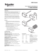
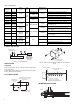
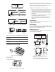
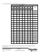
Table Of Contents
- Application
- Features
- SPECIFICATIONS
- TYPICAL APPLICATION
- INSTALLATION
- Inspection
- DUCT INSTALLATION
- IMMERSION INSTALLATION
- Model 20-782 Copper Well (Std.)
- Model 20-805 Stainless Steel Well
- Model 20-803 Adaptor with Model 20-778 Copper Well
- Figure-4 Series Immersion Well Pipe Installation and Dimensions.
- OUTSIDE WALL INSTALLATION
- ADJUSTMENTS
- “Zero” Adjustment
- MAINTENANCE
- FIELD REPAIR
- DIMENSIONAL DATA

2 © Copyright 2010 Schneider Electric All Rights Reserved. F-25908-4
TYPICAL APPLICATION
Figure-1 Typical Application.
INSTALLATION
Inspection
Inspect the package for damage. If damaged, notify the appropriate
carrier immediately.
If undamaged, open the package and inspect the device for obvious
damage. Return damaged products.
DUCT INSTALLATION
Figure-2 Surface Mounting Hole Dimensions and Duct Installation
Detail.
Figure-3 Averaging Element
IMMERSION INSTALLATION
Table-1 Model Chart.
TAC
Model No.
Replaces
Range
(non-adjustable)
°F (°C)
Span
°F
(°C)
Mounting
Maximum Temp.
of Thermal
Element °F (°C)
Sensing Element Description
2252-510 T150-1011
40 to 140
(4 to 60)
100
(56)
Duct or immersion
256 (124)
Rigid element, 1/4 x 9-3/8 in. long (6 x 238 mm)
2252-501 T150-1012
Duct
Averaging element, 20 ft. long (6.1 m)
2252-502 T150-1013 Rigid (coiled) element, 10 in. long (254 mm)
2252-250 T150-1021
0 to 100
(-18 to 38)
Duct or immersion
216 (102)
Rigid element, 1/4 x 9-3/8 in. long (6 x 238 mm)
2252-251 T150-1022
Duct
Averaging element, 20 ft. long (6.1 m)
2252-252 T150-1023 Rigid (coiled) element, 10 in. long (254 mm)
2252-610 T150-1031
40 to 240
(4 to 115)
200
(111)
Duct or immersion
471 (244)
Rigid element, 1/4 x 7-1/16 in. long (6 x 179 mm)
2252-635 T150-1035
Remote bulb, 1/4 x 10-1/2 in. long (6 x 267 mm) with
9-ft. Capillary (2.7 m)
2252-110 T150-1041
-40 to 160
(-40 to 71)
391 (199)
Rigid element, 1/4 x 7-1/16 in. long (6 x 179 mm)
2252-703 T150-1046
Duct or outdoor air
Remote bulb, 1/4 x 2.5 in. long (6 x 64 mm) with 42 in.
(1.1 m) capillary
2252-151 T150-1054
-25 to 125
(-32 to 52)
150
(84)
241 (116)
Remote bulb, 1/4 x 4 in. long (6 x 102 mm) with 36 in.
(0.91 m) capillary
2252-655 T150-1055
Remote bulb, 1/4 x 10-1/2 in. long (6 x 267 mm) with 9
ft. (2.7 m) capillary
2252-662 T150-1062
30 to 80
(-1 to 27)
50
(28)
Duct
138 (59) Averaging element, 20 ft. long (6.1 m)
2252-273 T150-1073
50 to 100
(10 to 38)
158 (70) Rigid (coiled) element, 10 in. long (254 mm)
2252-701 T150-1082
50 to 150
(10 to 66)
100
(56)
266 (130)
Averaging element, 20 ft. long (6.1 m)
2252-702 T150-1083 Rigid (coiled) element, 10 in. long (254 mm)
B
CRMS
Receiver Controller
M
M
21-038
2252
Pneumatic
Temperature
Transmitter
3-15 psig
Branch Air to
Control Device
3-7/16
(87)
21/32
(17)
1" (25.4) Hole for rigid (coiled)
thermal element 1/2" (13) hole
for all others.
Mounting hole
for No.8 screw.
(2 holes)
1-23/32
(87)
Dimensions shown
are in inches (mm).
No.8 Sheet Metal
Screw (Typical)
Wire Tie (Typical)
Turns of bulb supported
by steel rod
Cutout in duct wall large
enough to pass coiled bulb
FLOW
1/2" NPT