
Product Overview
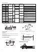
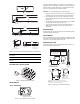
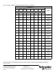
Table Of Contents
- Application
- Features
- SPECIFICATIONS
- TYPICAL APPLICATION
- INSTALLATION
- Inspection
- DUCT INSTALLATION
- IMMERSION INSTALLATION
- Model 20-782 Copper Well (Std.)
- Model 20-805 Stainless Steel Well
- Model 20-803 Adaptor with Model 20-778 Copper Well
- Figure-4 Series Immersion Well Pipe Installation and Dimensions.
- OUTSIDE WALL INSTALLATION
- ADJUSTMENTS
- “Zero” Adjustment
- MAINTENANCE
- FIELD REPAIR
- DIMENSIONAL DATA

F-25908-4 © Copyright 2010 Schneider Electric All Rights Reserved. 3
Model 20-782 Copper Well (Std.)
Model 20-805 Stainless Steel Well
Model 20-803 Adaptor with Model 20-778 Copper Well
Figure-4 Series Immersion Well Pipe Installation and Dimensions.
Note: Use thermo-conductive paste (M-500) for best sensor
performance.
Note: Maximum pressure rating of wells and adaptors is 500 psig
(34.5 bar).
OUTSIDE WALL INSTALLATION
Figure-5 Outside Wall Mounting Detail.
ADJUSTMENTS
“Zero” Adjustment
Figure-6 “Zero” Adjustment Screw Location.
The 2252 transmitters feature an accessible “zero” adjustment. In
applications where it is desirable to obtain very accurate temperature
indication (and/or control) within a given narrow temperature span,
minor “zero” adjustments may be made as follows:
Caution: Do not attempt adjustment of transmitter span.
1. With the cover removed, measure the sensed temperature and
transmitter output pressure with suitably accurate instruments.
2. Turn adjusting screw “A” to increase or decrease the output
pressure as required (clockwise turn increases output pressure).
See Figure 6.
• The air supply to the restrictor must be 20 psig ±0.5 psi (138 kPa
±3.4 kPa) and must be clean, dry, oil free air.
• The proper size restrictor must be used (0.0063" diameter, 1
SCFH; see “Accessories”), and must be clean and free of
obstructions.
MAINTENANCE
Regular maintenance of the total system is recommended to assure
sustained, optimum performance.
FIELD REPAIR
None. If transmitter does not function properly when properly installed
with clean 1.0 scfh (0.0063" diameter) restrictor or restrictor-tee and
20 psig clean, dry air supply, replace entire unit.
DIMENSIONAL DATA
Dimensions shown in inches and millimeters. Refer to Figure-7 for
general description and dimensions.
Figure-7 2252 Series Transmitter Dimensions.
45
FLOW
Coupling Welded at
45 Angle
10-17/32
(267)
9-3/16
(233)
3/8 Dia.
(10)
7/8 Hex
1/2-14 NPT
17/32 EFF. Thd. Lg.
(13)
Dimensions shown
are in inches (mm).
10-7/16
(265)
7-1/32
(179)
3/8 Dia.
(10)
7/8 Hex
1/2-14 NPT
17/32 EFF. Thd. Lg.
(13)
3/4 Hex
Dimensions shown
are in inches (mm).
7-1/32
(179)
11/16
(17)
2-13/16
(71)
9/16
(14)
1/4
(6)
5/16 Dia.
(8)
7/8 Hex
1/2 - 14 NPT
3/4 Hex
Set Screw
Locking Rings(Typical)
7/16-24 NPT
Dimensions shown
are in inches (mm).
Adjusting Screw "A"
1-1/4
(32)
1-3/8
(35)
1-3/4
(44)
A
3-7/16
(87)
3-3/4
(95)
3-1/16
(78)
1/4
(6.4)
Remote Bulb
Element
11/64 Dia.
(4.4)
2 Holes
1/16
(1.6)
3/4
(19)
Rigid (Coiled)
Element
9-13/16 Long
(249)
5/64 (2)
Averaging
Element
20' Long (6.1M)
1/4
(6.4)
3/8
(10)
1/8
NPT
Rigid Element
Temperature Range Dim "A"
0 to 100 F (-18¡ to 38¡ C)
40 to 140 F (4¡ to 60¡ C)
-40 to 160 F (-40¡ to 71¡ C)
40 to 240 F (4¡ to 116¡ C)
9 3/8 (238)
7 1/16 (179)
No. 10-24 UNC 2B
(Locking set screw for well
on rigid stem elements
only use 3/32 allen wrench).
1 2252-655 Remote bulb model, with 9 ft. (2.7m)
capillary, has 1/4" OD copper sleeve silver-soldered
to bulb, for use with immersion wells.
Dimensions shown
are in inches (mm).