
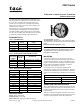
Product Overview

Printed in U.S.A. 8-08 © Copyright 2008 TAC All Rights Reserved. F-24544-2
The 2323 Differential or Static Pressure Transmitters have
been designed to sense differential or static pressure across
fans, coil, filters, or between two reference points, and
transmit a 3 to 15 psig signal to controlling and indicating
devices such as receiver controllers, receiver gauges, and
sensitive pressure switches.
These devices are one-pipe transmitters which require an
external restrictor in the supply line. Their design features
pneumatic feedback, which ensures accuracy and stability
over the entire operating range. Mounting ears are provided
for strain-free mounting on ducts or other flat surfaces.
ORDERING DATA
SPECIFICATIONS
Action: Direct, proportional.
Output pressure: 3 to15 psig
Main air pressure: 20 psig operating, 30 psig max.
Table-1 TRANSMITTERS.
UNI-LINE
NUMBER
REPLACES
MODEL
RANGE
2323-500 P323-03 0" to 3" W.C.
2323-503 P323-01 -0.5" to +0.5" W.C.
2323-504 P323-10 0" to 10" W.C.
2323-505 P323-0025 -0.05" to +0.20" W.C.
Table-2 ACCESSORIES & REPLACEMENT PARTS.
TAC
WHOLESALE
NUMBER
REPLACES
MODEL
DESCRIPTION
20-877 N1-3 Static pressure tip - 1/4" O.D.
20-944 N4-32 Restrictor tee, copper tubing
21-038 N100-0010 Restrictor tee, polyethlene tubing
21-153 N100-2501 In-line restrictor
Table-3 RECIEVER GAUGE OVERLAYS.
21-764 23-63 2" 0"to 3"
21-768 24-63 2-1/2" 0" to 3"
21-773 25-63 3-1/2" 0" to 3"
21-763 23-62 2" -0.5" to +0.5"
21-767 24-62 2-1/2" -0.5" to +0.5"
21-772 25-62 3-1/2" -0.5" to +0.5"
21-765 23-64 2" 0" to 10"
21-770 24-64 2-1/2" 0" to 10"
21-774 25-64 3-1/2" 0" to 10"
21-834 23-66 2" -0.5" to +0.20"
21-578 24-66 2-1/2" -0.5" to +0.20"
21-579 25-66 3-1/2" -0.5" to +0.20"
Air consumption: 29 SCIM
Air connections: Nipples for 1/4" O.D. polyethylene tubing
except LO and HI ports which require 3/8" O.D. Polyethylene
tubing
Maximum ambient temperature: 140°F
Caution:
THIS DEVICE SHOULD BE INSTALLED BY A
QUALIFIED PERSON WITH DUE REGARD FOR SAFETY,
AS IMPROPER INSTALLATION COULD RESULT IN A
HAZARDOUS CONDITION.
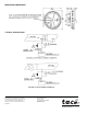
MOUNTING
To be used on control air only. Do not use on any other
medium. Using the integral mounting flange, the unit may be
mounted using two machine screws or self-tapping screws.
Two No. 10 x 5/8" pan head self-tapping screws are supplied.
Be sure that the transmitter is mounted in a horizontal
position with “THIS SIDE UP” on the top.
The sensing lines for the transmitter should be sized
according to the length of run to the sensing head. By strictly
adhering to the following table, there should be no adverse
effects on the transmitted signal. Sensing lines must be leak
free.
OPERATION AND MAINTENANCE
When a differential pressure is sensed between the high and
low pressure sensing lines, this device will transmit a 3 to 15
psig signal proportional to the pressure sensed to a remote
readout location.
There is no maintenance required on this unit. In the event of
a malfunction, make sure all air lines and restrictors are clean
and open. If still inoperable, replace with a new device.
SENSING TUBE
Length Minimum O.D.
Up to 200’ 1/4"
200’ to 500’ Max. 3/8"
2323 Series
Differential or Static Pressure Transmitter
General Instructions