TAC Pneumatic Products Catalog
General Information TAC TAC is a Schneider Electric Company with a long tradition of global leadership in building controls technology. We off the most extensive line of controls and components available to today’s market, including valve bodies, valve assemblies, actuation devices and sensors, as well as interfaces, and automated systems that link these products and other building systems together.
ii © Copyright 2006 TAC. All Rights Reserved.
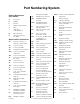
Part Numbering System Primary Designation (First Letter) HS humidity sensor, electronic A Accessories HSP H Humidity humidity transmitter, electronic P Pressure S Switch or Step Controller V Valve C Controller or Controlled Device MA M Motor (Actuator) MC R Receiver-Controller or P.E.
iv © Copyright 2006 TAC. All Rights Reserved.
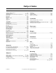
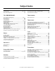
Subject Index Accessories Bulb Wells Actuator Shaft Extension ................................................. 166 Adjustment Cover ................................................... 161, 162 Aspirating Box for T-Series (2 x 2 in.) Devices .................... 1 Back Plate ............................................................... 160, 162 Backplate ......................................................................... 183 Ball-joint ..............................................................
Subject Index Mounting Post .................................................................. 178 Mounting Ring ......................................................... 157, 159 Offset Mounting Bracket .................................................. 178 Pneumatic to Electric Pressure Switches, Two-Position ....75 Pneumatic-Electric High/Low Alarm Switch .......................85 Pneumatic-Electric Switches ..............................................
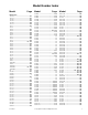
Model Number Index Model Page Numerics Model Page 100-13 .......................................... 163 100-17 .......................................... 163 100-25 .......................................... 163 100-47 .......................................... 164 100-49 .......................................... 164 100-71 .......................................... 164 10-11 ............................................ 157 10-15 ................................................ 1 10-22 ...............
Model Number Index Model Page 2216-526 .............................. 120, 122 22-180 .......................................... 187 22-181 .......................................... 187 2218-132 ...................................... 121 2218-133 ...................................... 121 2218-134 ...................................... 121 2218-142 ...................................... 121 22-183 .......................................... 187 2218-301 ...................................... 125 22-184 ..
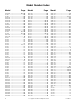
Model Number Index Model Page Model Page A201 ............................................... 41 A203 ............................................... 41 A204-03 .......................................... 41 A204-04 .......................................... 41 A205-01 .......................................... 41 A205-02 .......................................... 41 A251-1 .............................................. 2 A252 ................................................. 2 A253-12 .................
Model Number Index Model Page C4X42 ............................................ 31 C4X62 ...................................... 26, 27 C5-42 ....................................... 26, 27 C5-46 ............................................. 27 C5-47 ............................................. 27 C6-42 ....................................... 26, 27 C6-43 ....................................... 26, 27 C6-46 ............................................. 27 C6-47 ............................................
Model Number Index Model MK-6611 MK-6621 MK-6801 MK-6811 MK-6821 MK-6911 MK-7101 MK-7121 MK-71xx MK-7821 MK-7921 MK-8801 MK-8811 MK-8821 MK-88xx MK-8901 MK-8911 MK-8921 MK-89xx Page ......................................... 55 ......................................... 55 ......................................... 55 ......................................... 55 ......................................... 55 ......................................... 55 ......................................... 57 .............
Model Number Index Model Page RKS-1001 .................................... 110 RKS-2001 .................................... 110 RKS-3002 .................................... 110 RKS-4002 .............................. 13, 110 RKS-5001 .................................... 110 RKSR-4000 ............................ 13, 110 RNG-12 ................................ 187, 188 RNG-6 .................................. 187, 188 S S510 ..................................... 113, 113 S511 ..........................
10-15 (20-695) Pneumatic Products -15 (205) Aspirating Box for T-Series (2 x 2 in.) Devices These aspirating boxes are designed to permit flush mounting of Txx (2 x 2 in.) pneumatic room thermostats where room decor, instrument protection, or other application requirements make this desirable. These aspirators use control system air on the venturi principle to induce the flow of room air across a thermostat sensing element. Features: • Attractive appearance.
A25x Series A25x Series Receiver Gauges Receiver gauges for continuous indication of temperature, differential static pressure, differential pressure, pressure, enthalpy, or humidity in conjunction with a transmitter-receiver system. Select “donut” type dials listed for required application. 30 20 40 50 60 10 70 80 0 Features: • Receiver-gauges receive output signals of pneumatic transmitters and provide readout of measured (and/or controlled) variables at convenient locations.
A25x Series Options — Receiver Gauge Dials. (Continued) Range 2 in. for A253-12 2-1/2 in. for A251-1 3-1/2 in.
A25x Series Typical Applications A25x Receiver Gauge M S M Branch Air to Control Device N100-0010 B M S R C Temperature Transmitter 3-15 psig P541 Receiver Controller Figure 1 Typical Application. Notes: Receiver-Gauges may be connected at any point in the line between the transmitter and the receiver-controller (i.e., on either side of the restrictor-tee). More than one receiver-gauge may be connected to the same line if required. 4 © Copyright 2006 TAC. All Rights Reserved.
AE-6xx, N100 Series AE-6xx, 100 eries Control Cabinets Control cabinets for mounting of electric, electronic, and pneumatic controls. Features: • A variety of control cabinets enables selection of the best unit to suit the application. • N100-9901 cabinet mounts up to 16 TAC PNEUMODULAR® components. • Also see TAC PNEUMODULAR® Control Panels (PCP) on page 187. AE-629 N100-9901 AE-662-501 AE-662-502 AE-662-503 AE-630 AE-631 AE-632 Model Chart Door Steel Gage Model No.
AE-6xx, N100 Series Model Chart (Continued) Model No. Description Dimensions WxH in. (mm) AE-630-101 Subpanel for AE-629 and AE-630, 16 gage, perforated for #8 Type A sheet metal screws, flanged 14-1/2 x 20 (368 x 508) AE-631-101 Subpanel for AE-631, 16 gage, perforated for #8 Type A sheet metal screws, flanged 22-1/2 x 28 (572 x 711) Specifications Construction Doors Locking type, supplied with keys, rigidly supported.
AK-42309-500 AK-4230900 Positive Positioning Relay Positive positioner pneumatic relay is used to accurately position an actuator stroke with respect to signal pressure from the controller. It can also be used to change the effective spring range of an actuator and increase the capacity of a controller.
AK-42309-500 Accessories Model No. TOOL-095-1 PKG-1089 Description Pneumatic calibration tool kit. Spring and feedback arm kit for AK-42309-500 (included with AK-42309-500). Typical Applications AK-42309-500 Output to Actuator B Pilot from Controller P M M Figure 1 Piping Connections. 8 © Copyright 2006 TAC. All Rights Reserved.
AK-52101 AK-52101 Differential Logic Module Relay Pneumatic differential logic module relay typically used for comparison of outdoor and return air enthalpy transmitters to position the outdoor and return air dampers, providing energy conservation, when the outdoor air enthalpy is higher than the return air enthalpy. Features: Compares two pneumatic signals; provides a high-gain pneumatic output pressure change based on the input signal comparison. Model Chart Model No.
AK-52101 Typical Applications Input Input 2 M Output M B 1 AK-52101 Figure 1 Piping Connections. HKS-8065 Enthalpy Transmitter Outdoor Air 2 M M AT-532-111-1-01 HKS-8065 Enthalpy Transmitter Return Air Output of Mixed Air 2 Controller 1 AT-532-111-1-01 1 2 Output of Logic Module 3 M B AK-52101 Logic Module 1 Relay Type or 20 psig Supply Air. 2 When temperature transmitters are used, the transmitters should be of the same range and span.
AKR-40605 AKR0605 Limiting, 1:1 Ratio Relay and Scale Plates 10 Pneumatic 1:1 ratio direct acting relay is used to limit minimum or maximum output pressure. The AKR-40605 can also be used as a manual positioner, 1:1 ratio relay, or lowest of two pressures selector. Relay will also increase the capacity of a controller (except when used as maximum output limiter or lowest pressure selector). 20 AKR-40605 AKR-40605 Shown with AK-53098 Scale Plate and Knob Model Chart Air Connection Code Model No.
AKR-40605 Accessories Model No. AK-53098 AK-53198 AK-53298 AK-53398 AK-53498 AK-53598 AK-53698 AK-53798 Description (Scale Plate and Knob Kits) 0 to 20 psig. % Min. Outdoor Air (O.A.). “Increase” CW. “Increase” CCW. “Close” CW. “Close” CCW. “Warmer” CW. “Warmer” CCW. Typical Applications Pilot Signal (input) B Output M M P AKR-40605 Minimum Output Limiting Application Shown Figure 1 Piping Connections. 12 © Copyright 2006 TAC. All Rights Reserved.
AKS-1100 AKS-1100 Receiver Controller Setpoint Adjuster and Scale Plates Setpoint adjuster and scale plates used to provide remote setpoint adjustment of RKS-2001, RKS4002, and RKSR-4000 receiver-controllers. May also be used to manually pilot pneumatic relays. Features: • Allows the setpoint of a pneumatic receiver-controller to be raised or lowered from a location up to 1000 ft. (305 m) from the receiver-controller. • Series available to work with various transmitter ranges.
AKS-1100 Accessory Scale Plates (must be ordered separately). Model No. Description For Use with the Following Transmitters AKS-1129 r5qF Scale AKS-1130 Closed Open AKS-1131 Open Closed AKS-1149 r5.5qC Scale AKS-1169 r20qF Scale AKS-1189 r8% R.H. Scale HKS-2033, -5033 AKS-1199 r2 in.
AL-15x Series AL-15x eries Solenoid Air Valve For applications where an electrical circuit is used to control a pneumatically operated device. Used to direct supply air to a pneumatic device when the coil is energized or de-energized depending on the supply and exhaust air connections. May be used for selection or diverting applications. Features: • High capacity of AL-15x Series allows operation of more devices. • Brass body receives 1/8 in.
AL-15x Series Typical Applications Typical Schematic Diagram Motor Starter L1 L2 L3 X1 A H O C Red Leads Green Lead AL-150 Bottom View (N.O.) Port 2 N.C. M 20 Port 3 N.O. Port 1 Common 120V H G PE 1 M Supply Fan Motor Humidifier Fan Room Humidistat (R.A.) H1 M B MB Exhaust M1 B M S To N.C. Steam Humidifier Outside Air Damper (N.C.) 8-13 psi (Typical) Branch (output) of mixed air temperature controller To Return (M2) Damper (N.O.) Positioner To Relief (M3) Damper (N.C.
AL-161-4 AL-161-4 Air Switching Valve Three-way air switching valve is used for central supply air changeover in dual pressure systems. Features: Compact size; large air capacity. Model Chart Flow Pattern Model No. AL-161-4 a Stem Up [No Air to Actuator] Stem Down [20 psig (138 kPa) Air to Actuator] Flow Closed Port Flow Closed Port B to ABa A A to AB a B AB Common. Specifications Construction Body Bronze. Actuator Die cast aluminum with replaceable neoprene diaphragm.
AL-161-4 Typical Applications Electric Time Switch L1 L2 AL-1xx Solenoid Air Valve (E/P Relay) M N.C. C N.O. 15 psi (103 kPa) AL-161-4 A Pressure Gauge 0-30 psig AB B Supply Main to Thermostats 20 psi (138 kPa) Figure 1 Typical Application. 18 © Copyright 2006 TAC. All Rights Reserved.
AL-17x Series, AL-18x Series AL-17x eries, AL-18x eries Solenoid Air Valves For applications where an electrical circuit is used to control a pneumatically-operated device. Used to direct supply air to a pneumatic device when the coil is energized or de-energized, depending on the supply and exhaust air connects. Features: • Open frame or junction box construction accommodates a wide variety of NEMA 1 mounting locations. • Available in 24, 120, 208, 240, or 480 Vac models. • Supplied with 18 in.
AL-17x Series, AL-18x Series Typical Applications AL-170 Solenoid Air Valve Fan Power Supply M N.C. 1 2 N.O. Exhaust 3 C Damper Actuator Exhaust Air from Building Exhaust Fan To Outdoors Damper (NC) (opens when fan runs) Figure 1 Typical Application Diagram. 20 © Copyright 2006 TAC. All Rights Reserved.
AL-19x Series AL-19x eries Solenoid Air Valve For applications where an electrical circuit is used to control a pneumatically operated device. Used to direct supply or control air to pneumatic devices when the coil is either energized or de-energized, depending on the supply and exhaust air connections. Features: • Plastic corrosion-resistant body provides long life. • Mounting bracket and fittings for 1/4 in. O.D. plastic tubing supplied with valve for simple, quick installation.
AL-19x Series Typical Applications Typical Schematic Diagram Motor Starter L1 L2 L3 X1 A H O C Red Leads AL-191 (120 V) Green Lead 120V H G (N.O.) Port 2 N.C. Port 3 N.O. M Exhaust Supply Fan Motor Humidifier Fan PE 1 Room Humidistat (R.A.) H1 M B MB M1 Port 1 Common M B M S Branch (output) of mixed air temperature controller To N.C. Steam Humidifier Outside Air Damper (N.C.) 8-13 psi (Typical) To Return (M2) Damper (N.O.) Positioner To Relief (M3) Damper (N.C.
AL-3xx Series AL-3xx eries Pressure Gauges Pressure gauges for continuous indication of air pressure in pneumatic control systems. Features: • Permits readout of main air pressure and/or output pressures of pneumatic control components. • 0 to 100 (0 to 700 kPa) and 0 to 30 psig (0 to 200 kPa or 0 to 210 kPa) models available. • Available in flush-mounted or stem-mounted models. 0 AL-323 Shown Model Chart Model No.
AL-7xxx Series AL-7xxx Series Unit Ventilator Sub-Panels Pneumatic unit ventilator sub-panels provide plug-in wiring of the various controls. Features: • Several different sub-panel assemblies, for use with unit-ventilators, provide standardized plug-in wiring of: - P.E. switches. - Electrical low-limit thermostats with manual or automaticreset. - Solenoid air valve (E.P. Relay). AL-7121 Model Chart Quantity of Items on Sub-Panel Model No. AL-7111 PC-151 P.E. Switch (DPDT) TC-5231 Low Temp.
C Series, CT Series (21 and 22 Series) Thermostat Covers C Ser CT Se (21 an 22 Se These thermostat covers are designed for use with 2 x 2 in. pneumatic controls only. All covers are supplied with a concealed setpoint adjustment cover (factory installed on the -403, -404, and -407 models). 0 5 The CTR-xx universal replacement cover kit includes a factory assembled standard cover with qF thermometer, setpoint, and three inserts for field configuration (Barber-Colman only).
C Series, CT Series (21 and 22 Series) Model Chart TAC Thermostat Covers with Robertshaw Logo. Cover Model No.
C Series, CT Series (21 and 22 Series) Thermostats for use with Robertshaw Logo Thermostat Covers. Cover Model No.
C Series, CT Series (21 and 22 Series) TAC Wholesale Thermostat Covers with Robertshaw Logo. Cover Model No.
C Series, CT Series (21 and 22 Series) Thermostats for use with Wholesale Robershaw Logo Thermostat Covers. Cover Model No.
C Series, CT Series (21 and 22 Series) TAC Thermostat Covers with Barber-Colman Logo. Cover Model No.
C Series, CT Series (21 and 22 Series) TAC Blank Thermostat Covers (No Logo) Cover Model No.
H18-301 (2230-018) H18-301 (2230-01 8) Room Humidistat The pneumatic room humidistat is a proportioning-type device designed to control pneumatic valves or damper actuators associated with heating or cooling coils, humidifiers, air washers, or other humidifying or dehumidifying equipment to maintain constant relative humidity. This device uses a highly sensitive hygroscopic nylon ribbon and a pilot bleed relay with pneumatic feedback.
H18-301 (2230-018) Specifications (Continued) Mounting Upright position on wall. Dimensions 2-1/32 H x 2-1/32 W x 1-3/8 D in. (52 x 52 x 35 mm). Accessories Model No. 6-371 10-50 10-53 10-57 10-58 10-59 10-62 10-63 10-64 10-66 10-72 10-73 10-76 10-77 10-78 10-80 10-82 10-82-SS 10-82-47 10-82-48 C10-42 C10-46 C15-42 MCS-GA N2-4 N5-49 N5-50 N5-52 N5-53 N5-95 Wholesale Model No.
H53-301 (2232-053) H53-301 (2232-053) Room Humidity Transmitter Humidity Transmitter measures room humidity and transmits a proportional pneumatic signal to a calibrated receiver gauge and/or receiver controller. The device is factory set to transmit a 3 to 15 psig signal over a 30 to 80% RH range. Features: • Highly sensitive nylon sensing element, temperature-compensated. • Linear response to room relative humidity changes. • Stable, force-balance operation. • Small size, attractive appearance.
H53-301 (2232-053) Accessories Model No. 6-371 10-53 10-57 10-58 10-59 10-62 10-63 10-64 10-66 10-72 10-73 10-76 10-77 10-78 10-80 10-82 10-82-SS 10-82-47 10-82-48 C15-42 MCS-GA N2-4 N4-32 N5-49 N5-52 N5-53 N100-0010 N100-2501 Wholesale Model No. 20-642 20-707 20-710 20-711 20-712 20-715 20-716 21-468 21-800 21-473 21-876 20-714 21-964 22-138 20-881 20-944 21-065 21-068 21-069 21-038 21-153 Description Mounting ring (use with mounting heads). Metal thermostat guard.
H150-100 (2232-150) H150-100 (2232-150 Duct Relative Humidity Transmitter The Relative Humidity Transmitter is designed to measure relative humidity in an air duct and to transmit a 3 to 15 psig pneumatic signal over its 0 to 100% R.H. span to remote controlling, indicating, and alarm devices such as receiver-controllers, receiver gauges, and sensitive pressure switches. Features: • Widest possible (0 to 100%) relative humidity range for 3 to 15 psig (20.7 to 103.4 kPa) output.
H150-100 (2232-150) Typical Applications M N.C. Steam Valve 8-13 psig S N100-0010 H150-100 Duct Humidity Transmitter V M B M M S R M NC NO C C To Steam Humidifier STM. S Vac Wire to Fan Starter R527 Series E/P Relay Receiver Controller (Reverse Acting) 1 H150-100 is usually located in the return (or exhaust) air duct, to measure space relative humidity.
HKS-2033, HKS-5033 HKS-2033 HKS-5033 Room/Duct Humidity Transmitters For proportional humidity control used with RKS Series receiver-controllers. May be used with calibrated gauges for continuous humidity indication at any local or remote position. Features: HKS-2033 • 10 to 90% relative humidly range for 3 to 15 psig (20.7 to 103.4 kPa) output. • Highly sensitive nylon sensing element, designed for duct insertion. • Pneumatic feedback for stable, repeatable operation.
HKS-2033, HKS-5033 Specifications (Continued) Mounting HKS-2033 Duct. HKS-5033 Wall (has beige plastic cover). Dimensions HKS-2033 4-3/16 H x 4 W x 2-1/16 D in. (106 x 102 x 52 mm); tube mounting hole diameter is 1-3/8 in. (35 mm) and tube insertion length is 4-1/4 in. (108 mm). HKS-5033 4-3/8 H x 2-3/4 W x 1-5/8 D in. (111 x 70 x 43 mm). Order fittings separately for type of wall construction. Accessories Model No.
HKS-8065 Duct Enthalpy Transmitter For proportional enthalpy control used with receiver-controller. For differential enthalpy control, two HKS-8065 are used with AK-52101 to determine if return or outdoor air has the higher enthalpy. May be used with receiver-gauges for continuous enthalpy indication at any local or remote position. HKS-8065 Features: • Designed to sense total heat (enthalpy) in air ducts.
A20x Series A20x Series Pressure Gauges Pressure gauges for continuous indication of air pressure in pneumatic control systems. 10 Features: • 0 to 30 psig models permit readout of main air pressure and/or output pressures of pneumatic control components. • 0 to 160 psig models permit readout of pressure in aircompressor receivers or high-pressure main air lines. • Available in flush-mounted, stem-mounted, bottommounted or lower-back mounted models.
M556 Series (2466 Series), M572 Series (2472 Series), M573 Series (2473 Series), M574 Series (2474 Series) M556 Series (2466 Series), M572 Series (2472 Series), M573 Series (2473 Pneumatic Damper Actuators These actuators are designed for use in pneumatic control systems to position air control dampers in response to signals from pneumatic controllers. The M556 is a large swivel-mounted actuator with an adjustable crank arm having a clamp to fit a 1/2 in. O.D. damper shaft.
M556 Series (2466 Series), M572 Series (2472 Series), M573 Series (2473 Series), M574 Series (2474 Series) Hesitation Actuator. Stroke Diaphragm Area Spring Range psig Mounting Description M583-0520 2 in. 7 sq. in. 1 to 4 and 8 to 12 Post-mtd. Actuator with stamped clevis, clevis pin and bracket; for use on air handlers where factory mounting has not been established. M584-0211 3 in. 11 sq. in.
M556 Series (2466 Series), M572 Series (2472 Series), M573 Series (2473 Series), M574 Series (2474 Series) 4 in. Stroke (11 sq. in.). Spring Range psig Model No. Mounting M574-2208 M574-2211 Right-angle 3 to 12 M574-2520 Post-mtd. M574-8208 Right-angle 4 to 8 M574-8211 M574-8520 Post-mtd. M574-3208 M574-3211 Right-angle 5 to 10 M574-3520 Post-mtd. Description Actuator with ball joint to accept 5/16 in. push rod. Actuator with complete linkage for 1/2 in. damper shafts.
M556 Series (2466 Series), M572 Series (2472 Series), M573 Series (2473 Series), M574 Series (2474 Series) Specifications Construction Housing Glass-filled nylon. Diaphragm Neoprene, rolling type. Shaft Stainless Steel on M556, M573, M574. Nickel plated steel on M572, M583, M584. Stroke Refer to Model Chart. Spring Retract actuator shaft on loss of air pressure. Ambient temperature limits -20 to 180qF (-29 to 82qC). Supply air pressure Clean, dry, oil free air required.
M556 Series (2466 Series), M572 Series (2472 Series), M573 Series (2473 Series), M574 Series (2474 Series) Accessories Model No. AM-112 AM-113 AM-115 AM-122 AM-123 AM-125 AM-125-048 AM-132 N5-75 N800-1403 N800-1404 N800-1414 N800-1415 M556 Kits Wholesale Model No. Description Slotted crank arm for 3/8 in. shaft Slotted crank arm for 1/2 in. shaft. Slotted crank arm for 7/16 in. shaft. Straight connector. Damper clip. 5/16 x 20 in. damper rod. 5/16 x 48 in. damper rod.
MK-2690 MK-269 Pneumatic Valve Actuator For proportional pneumatic control of 1/2 in. to 2 in. VB-7xxx Series valves (subject to close-off ratings) and discontinued 1/2 in. to 1-1/4 in. VB-9xxx valves. Features: • Compact size with 6 in.2 (39 cm2) effective area. • Rugged die cast aluminum housing. • Replaceable beaded molded neoprene diaphragm. Model Chart Nominal Spring Rangea (Spring Color Code) Model No.
MK-3xxx Series, MK4-3xxx Series MK-3xxx Series, MK4-3xxx Series Pneumatic Damper Actuators Proportional pneumatic actuator with 8 in.2 (52 cm2) effective area used to control dampers, mixing boxes, air valves, etc., in heating, ventilating, and air conditioning systems. Features: • Rugged cast aluminum bodies. • Long lasting rolling diaphragm. • Provisions for adjustable stroke-stop. MK-31xx Series MK-38xx Series Model Chart Maximum Forceb Nominal Torque Return Stroke Model No.
MK-3xxx Series, MK4-3xxx Series Model Chart (Continued) Maximum Forceb Return Stroke Nominal Operating Range Starting Pressure Nominal a Stroke Model No. psig kPa psig 3-1/2 (89), adjustable 2 to 4 (51 to 102) 52 (231) 12 (53) 8 to 13 55 to 90 8 r1 55 r7 MK-3141 3 to 13 21 to 90 3 non-adj. 21 non-adj. MK-3151 3 to 6, 9 to 12 21 to 41, 62 to 83 MK-3161 3 to 6, 21 to 41, 11 to 17 76 to 117 MK-3821 8 to 13 55 to 90 MK4-3821 e lb (N) in.
MK-3xxx Series, MK4-3xxx Series Accessories Model No. AK-42309-500 AM-111 AM-112 AM-113 AM-115 AM-122 AM-123 AM-125 AM-125-048 AM-132 AM-161-3 AM-301 AM-530 AM-532 AM-533 AM-534 AM-535 AM-536 AM-545 TOOL-095-1 Maintenance Parts PND-45-343 PND-45-345 PND-45-348 PND-002-1 PND-91 50 Description Positive positioner and linkage. Crank arm for 5/16 in. diameter damper shaft. Crank arm for 3/8 in. diameter damper shaft. Crank arm for 1/2 in. diameter damper shaft. Crank arm for 7/16 in. diameter damper shaft.
MK-44xx Series, MK4-44xx Series MK-44x Series, MK4-44 Series Damper Actuators, Proportional For proportional pneumatic actuator with 11 sq. in. (71 cm2) effective area used to control damper and air valves in heating, ventilating, and air conditioning systems. Features: • Rugged cast aluminum body. • Special linkage permits easy adjustment of stroke to suit various applications. • Hesitation and non-hesitation models available. Model Chart Maximum Forcea Model No.
MK-44xx Series, MK4-44xx Series Specifications Construction Housing Die cast aluminum. Diaphragm Replaceable beaded molded neoprene (Part number PNV-2). Stroke Linkage Adjustable 1/2 to 3 in. (13 to 76 mm); factory set for 2 in. (51 mm). Diaphragm Factory set for 1 in. (25 mm). Nominal Damper Area Actuator sizing should be done in accordance with damper manufacturer’s specifications. Start point Adjustable. Refer to Description Model Chart.
MK-46xx Series, MK4-46xx Series MK-46x Series, MK4-46 Series Valve Actuators, Proportional For proportional pneumatic actuator with 11 sq. in. (71 cm2) effective diaphragm area used to control 1/2 in. to 2 in. VB-7xxx series valves and SP-3xx00 step controllers. Features: • Rugged die cast aluminum construction. • Rolling diaphragm. • Multiple spring ranges for various applications. • Adjustable start point (refer to Specifications). • 1/2 in. nominal stroke.
MK-46xx Series, MK4-46xx Series Accessories Model No. AK-42309-500 TOOL-095-1 Maintenance Parts PNV-002 PNV-004-2 PNV-232 PNV-238 PNV-239 PNV-251 54 Description Positive positioner and linkage; use with MK-46X1. Pneumatic calibration tool kit. Diaphragm. Piston. 10 to 11.25 psig spring for MK-4621-422. 3 to 6 psig spring for MK-4601. 10 to 13 psig spring for MK-4621. High temperature diaphragm. © Copyright 2006 TAC. All Rights Reserved.
MK-6xxx Series Valve Actuators, Proportional Proportional pneumatic actuator with 50 sq. in. (323 cm2) effective diaphragm area used to control 1-1/2 in. to 2 in. VB-7xxx series, 2-1/2 in. to 5 in. VB-8xxx series, 2-1/2 in. to 4 in. discontinued VB-9xxx series and 4 in. to 6 in. discontinued VB-9323 series valves. Features: • Rugged die cast aluminum construction. • Rolling diaphragm. • Three spring ranges for various applications. • Start point adjustable r2 psi.
MK-6xxx Series Accessories Model No. AK-42309-500 TOOL-075 TOOL-095-1 Linkage AV-430 AV-495 AV-497 Maintenance Parts MK-68xx Series (1 in. stroke) PNV-245-103 PNV-245-105 PNV-245-108 MK-66xx Series (1/2 in. stroke) PNV-245-013 PNV-245-015 PNV-245-018 MK-69xx Series (1-1/2 in. stroke) PNV-245-148 PNV-245-145 All Series PNV-202 56 Description Positive positioner and linkage. Spring compression tool. Pneumatic calibration tool kit. Valve Body Series VB-7xx3, 1-1/2 to 2 in. VB-7xx4, 1-1/2 to 2 in.
MK-71xx Series, MK4-71xx MK-71x Series, MK4-71 Damper Actuators, Proportional For proportional pneumatic actuator with 20 sq. in. (129 cm2) effective area used to control damper and air valves in heating, ventilating, and air conditioning systems. Features: • Rugged cast aluminum body. • Completely enclosed spring. • Long lasting rolling diaphragms. Model Chart Maximum Forcea Return Stroke Model No.
MK-71xx Series, MK4-71xx Specifications Construction Housing Die cast aluminum. Diaphragm Replaceable beaded molded neoprene. Stroke Nominal 4-1/2 in. (114 mm), adjustable 4 to 5 in. (102 to 127 mm). Nominal Damper Area Actuator sizing should be done in accordance with damper manufacturer’s specifications. Start point Adjustable, refer to Description Model Chart. Spring Retracts actuator crank arm on loss of air pressure. Maximum air pressure 30 psig (207 kPa).
MK-7821, MK-7921 MK-782 MK-792 Floor Mounted Damper Actuators For proportional pneumatic actuator used to control inlet vanes on small and medium size fans or large jackshafted dampers. Features: • Dual actuators, operating a single shaft and piloted by a position, provide maximum capacity for heavy loads. • Lever with multiple holes facilitates stroke adjustment to suit various applications. • Rigid steel base provides firm actuator support. MK-7921 Model Chart Stroke in. (mm) Model No. Diaph.
MK-7821, MK-7921 Specifications Construction Housing Die cast aluminum. Diaphragm Replaceable beaded molded neoprene. Assembly Actuator(s) and positive positioner (AK-42309-500) are factory mounted on a frame of channel and angle iron. Rotary output Provided by a driving lever arm connected to a bearing supported jackshaft. Stroke Rotary output of 60q driving lever arm connecting point adjustable from 4 to 13 in. (102 to 330 mm), in 1 in. (25.4 mm) increments, from centerline of jackshaft.
MK-88xx Series, MK-89xx Series MK-88x Series, MK-89x Series Valve Actuators, Proportional Proportional pneumatic actuator with 100 in.2 (645 cm2) effective area. MK-88xx Series used to control 2-1/2 in. through 4 in. valves requiring 1 in. stroke. MK-89xx Series used to control 5 in. and 6 in. valves requiring 2 in. nominal stroke. Used with VB-931x and discontinued VB-921x, VB-922x valves. Features: • Heavy duty aluminum construction.
MK-121xx Series MK-121xx Series Damper Actuators, Proportional For proportional pneumatic actuator with 3 in.2 (19 cm2) effective area used to control small dampers and mixing boxes. Features: • All-plastic construction. • Meets UL-465 requirements for air plenum mounting. • Ideal for VAV terminal unit control. Model Chart Maximum Forcea Model No. Nominal Operating Stroke Range psi MK-12100 3 to 8 MK-12110 5 to 10 MK-12120 8 to 13 MK-12140 3 to 13 in.
MK-121xx Series Accessories Model No. AM-111 AM-112 AM-113 AM-115 AM-122 AM-123 AM-125 AM-125-048 AM-132 AM-161-3 TOOL-095-1 F-27383-1 Description Crank arm for 5/16 in. diameter damper shaft. Crank arm for 3/8 in. diameter damper shaft. Crank arm for 1/2 in. diameter damper shaft. Crank arm for 7/16 in. diameter damper shaft. Linkage connector straight type. Damper clip. 5/16 x 20 in. damper rod. 5/16 x 48 in. damper rod. Ball joint connector. Damper linkage kit (AM-113 crank arm and AM-132 connector).
N100-25xx Series N100-25xx Series Pneumatic Limit Controls These controls open an integral pneumatic switch when sensed temperature reaches the control setpoint. DE G. C U T I N 55 FA HR 45 50 35 40 25 30 DE 15 20 G. FA C U T O U T HR PU SH TO RES ET Features: • Reduces installation cost when temperature sensing point is located a considerable distance from the motor starter of an air-handling unit supply fan.
N100-2511 N100-2 Pneumatic Liquid Flow Switch The control port opens on no flow and closes on liquid flow. Features: • Used with P/E Switch, reduces installation cost when flow sensing location is located a considerable distance from the desired electrical switching point. • If used with a DPDT P/E Switch, one circuit can be used to stop (or start) a motor, while the other circuit closes to initiate an alarm. • Paddles for 1 in., 2 in., and 3 in. pipe included. Model Chart Model No.
N100-4017 (2364-202) N100-401 (2364-202 Low Differential Pneumatic-Electric Switch The pneumatic-electric switch features a SPDT narrow differential switch which makes it suitable for use with wide span pneumatic transmitters in such applications as alarm initiation and outdoor changeover of heating and cooling functions. Features: • Narrow-differential P.E. switch can be used with any type of pneumatic transmitter to initiate an alarm caused by either a high or low alarm condition.
N800-0555 Series Positive Positioning Relay The N800-0555 is used with M556 (6 in. stroke), M573 (3 in. stroke), and M574 (4 in. stroke) damper actuators. The N800-0555 is pilot-operated, providing excellent response to small signal pressure changes from the controller. Pilot-operation also provides maximum resistance to actuator shaft displacement caused by outside force changes.
N800-0555 Series Model Chart (Continued) Feedback Springs. Positioner Feedback Spring Selection Actuator Stroke Part No. 3 in. M573 Series 4 in. For Span of: Model No. 3 psi N800-2277 5 psi N800-2257 M574 Series 6 in. M556 Series 10 psi N800-2267 3 psi N800-2278 5 psi N800-2258 10 psi N800-2268 3 psi N800-2279 5 psi N800-2259 10 psi N800-2269 Positioner Kits.a Wholesale Kit No. For Span of: 2850-028 Model No. Wholesale Model No. 3 in. M573 Series 2473 Series 4 in.
P301 Series (2301 Series) Pressure Transmitters The pneumatic pressure transmitters are designed to measure either air or fluid pressures. All models transmit a fixed-span, 3 to 15 psig output signal proportional to input pressure to controlling and indicating devices such as receiver-controllers, receiver gauges, and certain pneumatic relays and alarm devices. These transmitters are available in various pressure ranges to meet most control system application requirements.
P323 Series (2323-5xx Series) P323 Series (2323-5xx Series) Differential or Static Pressure Transmitters The P323 Series differential or static pressure transmitters have been designed to sense differential or static pressure across fans, coils, filters, or between two reference points and to transmit a 3 to 15 psig signal to controlling and indicating devices such as receiver controllers, receiver gages, and sensitive pressure switches.
P323 Series (2323-5xx Series) Specifications (Continued) Air capacity 48 scim. Calibration Factory set. Mounting Transmitter must be mounted in a horizontal position with the correct side up. Dimensions 5-9/16 H x 5-5/16 W x 2-11/16 D in. (141 x 135 x 69 mm). Weight 0.5 lb (227 g). Accessories Model No. A251-1 A252 A253-12 AP-302 AP-305 N4-32 N100-0010 N100-2501 Wholesale Model No. A253-12 2422-002 2422-003 — — 20-944 21-038 21-153 Description 2-1/2 in. gauge. 3-1/2 in. gauge. 2 in. gauge.
P541 Series (2341-5xx Series) P541 Series (2341-5xx Series) TAC PNEUMODULAR £ Receiver Controller The receiver controllers are used with remote pneumatic transmitters to provide proportional control in pneumatic control systems. They are designed primarily for use with pneumatic transmitters; however, they may be used with any pneumatic device having an output of 3 to 15 psig, such as thermostats or humidistats.
P541 Series (2341-5xx Series) Setpoint Dial Labels (order separately, continued). Model No. Wholesale Model No. Range Model No. Wholesale Model No. Range 300-33 21-458 0 to 2 in. W.C. 300-58 21-884 300-34 21-459 0 to 7 in. W.C. 300-70 21-889 0 to 300 psig 300-35 21-460 30 to 80% R.H. 300-71 300-46 21-790 -0.5 to +0.5 in. W.C. 300-72 21-890 0 to 100% R.H. 0 to 50 psig 0 to 100 psig 300-95 0 to 1.0 in. W.C. 300-80 21-891 0 to 2000 FPM 300-47 21-791 0 to 3 in. W.C.
P541 Series (2341-5xx Series) Typical Applications Active Connections. Port Connected to B Branch output. M Main air. S Primary signal input. R Reset signal input. C Control point adjustment. M N100-0010 Primary Temperature Transmitter 3-15 psig M N100-0010 Secondary Temperature Transmitter 3-15 psig M Branch Air to Control Device B M S R C P541 Receiver Controller 1 Remote control point adjust. M 1 S2 M B S1 S510 Gradual Switch Figure 1 Typical Application.
PC-1xx Series PC-1xx Series Pneumatic to Electric Pressure Switches, Two-Position For on-off control of electrical devices such as air compressors, fans, pilot lights, etc., by the use of a predetermined air pressure signal. Features: • A variety of Pressure-to-Electric (P.E.) Switches permits two-position electrical switching from either modulating or two-position pneumatic signals.
PC-1xx Series Electrical Ratings. Model No. PC-110 PC-131 PC-132 PC-151 Volts (Vac) FLA Amps LRA Amps Non-Ind. Amps Pilot Duty VA 100 24 16 120 13.8 82.8 16 650 208 9.6 57.6 9.6 750 240 8.3 49.8 8.3 750 277 7.2 120 12 72 12 208 12 72 12 240 12 72 12 277 12 120 6 36 10 208/240 3 18 8 277 7.2 125 at 120/600 Vac 125 at 24/277 Vac Accessories Model No. For PC-110 only AK-52582 AD-8953 76 Description Bracket for track mounting.
PKSR-9001, PKSR-9002 PKSR9001, PKSR9002 Differential Pressure Transmitter For transmitting a fixed span 3 to 15 psig (21 to 103 kPa) pneumatic signal which is proportional to a differential pressure being sensed. The output signal can be used as an input for receiver-controllers or gauges for differential pressure indication. Features: • Permits remote readout of differential water pressure on receiver-gauge, and control from a convenient location.
PKSR-9001, PKSR-9002 Accessories Model No. A251-1 A252 A253-12 AT-532-098-1-1 AT-532-098-1-2 AT-532-098-1-3 N100-0010 N100-2501 N4-32 Wholesale Model No. 2422-001 2422-002 2422-003 21-038 21-153 20-944 Description Receiver gauge. Receiver gauge. Receiver gauge. Restrictor tee for 1/4 in. copper compression fitting. .005" restrictor (Red). .010" restrictor (Blue). Restrictor tee for use with 1/4 in. or 5/32 in. I.D. plastic tubing. In-line restrictor. Restrictor tee, copper tubing.
R432 Series (2372 Series) R432 Series (2372 Series) High Pressure Selector Relay and Low Pressure Selector or Booster Relay The pressure selector relays are designed for use in pneumatic control systems where the application requires the comparison, selection, and transmission of the higher or lower of two proportional signals. R432-11 can also be used as a booster relay. R432-2 High Pressure Selector R432-11 Low Pressure Selector or Booster Relay Features: • Relays are non-adjustable.
R432 Series (2372 Series) Typical Applications Thermostat (D.A.) M M B M M B M S N.O. Heating Valve B Thermostat (D.A.) R432-11 Low Pressure Selector Figure 1 R432-11 Low Pressure Selector Relay. M B M Thermostat (D.A.) M M S To Additional Heating Valves in the Same Area B R432-11 Booster Relay N.O. Heating Valve Figure 2 R432-11 Used as Booster Relay. Thermostat (D.A.) M M B M M B Humidistat (D.A.) N.O. Heating Valve 2 to 7 psi S M B N.C.
R435 (2374-401) R435 (2374-4 Air Motion Relay This relay is used to sense suction and/or discharge pressures across a coil or fan and control pneumatic damper actuators or valves piped downstream from this device. By the use of sensing lines located at a fan suction and discharge and piped to the low and high ports of this relay, this device is able to detect whether or not a fan is operating.
R435 (2374-401) Typical Applications Restrictor M M B Room Thermostat V Damper Actuator LO S Airstream Thermostat HI R435 Air Motion Relay Control Valve Pressure Sensing Lines Figure 1 Typical Unit Ventilator Control Application. 82 © Copyright 2006 TAC. All Rights Reserved.
R436 R436 Air Differential Pressure Switch The R436 differential pressure switch is a sensitive and reliable device for remotely sensing the operation of fans or blowers associated with ducted ventilating systems, and for sensing static pressure drop across filters. Pressure differentials as small as 0.05 in. WG are sufficient to actuate the SPDT contacts, which in turn operate remote status indicators, alarms, or control circuits of other devices. Features: • Different setpoint adjustable from 0.
R436 Typical Applications Diaphragm Connections Electrical Refer to figure below. For positive pressure only, connect sampling line to port E; port F remains open to atmosphere. Before any pressure is applied to the diaphragm, the switch contact rests in the N.C. position (see figure below). Upon application of sufficient pressure to actuate the switch, the contact transfers to the N.O. position. Connect control, status, and/or alarm circuits, as shown.
R470 (2386-601) R470 (2386-6 Pneumatic-Electric High/Low Alarm Switch The switch is used to provide high and low signal alarm. Two independently adjustable SPDT switches provide 3 to 15 psig high and low alarm contact capability in this single device. Features: • The R470 has very narrow switching differential, and can be used with any pneumatic transmitter to set two independent high and low alarm points within the range of the transmitter.
R , 2R47 64-200 2 Ser ies) R471, R472 (2364-200 Series) Pneumatic-Electric Switches The pneumatic-electric switches are used in control systems requiring conversion of gradual air pressure changes to positive electrical switching actions. The R471-1 has a single SPDT switch for switching a single circuit. The R472-1 has two SPDT switches for switching two separate circuits simultaneously. Features: • Fixed-differential P.E.
R471, R472 (2364-200 Series) Typical Applications Pilot Light (lights when electric heat is on) N H C Thermostat (R.A.) M NO NO C Wire to energize electric heating element. M B R472-1 Pneumatic Electric Relay Figure 1 Typical Application (R472-1 shown). F-27383-1 © Copyright 2006 TAC. All Rights Reserved.
R500 (2351-001) TAC PNEUMODULAR £ Integral Relay with Capacity Tank The integral relay is a modulating device used with a proportional controller in applications where it is necessary to maintain the value of a controlled variable within close limits.
R500 (2351-001) Specifications (Continued) Dimensions R500 2-1/16 H x 1-7/8 W x 2-9/16 D in. (52 x 48 x 66 mm). K500 7-1/2 L x 2 Dia. in. (191 x 51 mm). Accessories Model No. K500 K502 TOOL-082 Wholesale Model No. Description Replacement timing tank kit. Optional mounting bracket. 5/64 in. hex wrench.
R503 Series (2353-5xx Series) R503 Series (2353-5xx Series) TAC PNEUMODULAR £ Diverting Relays The R503-1 and R503-2 diverting relays are snap-acting devices with adjustable setpoints. They are designed for a variety of switching and interlocking functions in pneumatic control systems where the application requires one or more of the following functions: feeding and exhausting branch lines, diverting a supply line to either one of two branch lines, or diverting one of two supply lines to one branch line.
R503 Series (2353-5xx Series) Specifications Control action Refer to Model Chart. Construction Glass-filled nylon. Maximum ambient temperature 140qF (60qC). Supply air pressure Clean, dry, oil free air required. Nominal 15 to 25 psig (103 to 172 kPa). Maximum 30 psig (207 kPa). Connections Barbed nipples for 1/4 in. O.D. polyethylene tubing. Air consumption 29 scim(7.9 mL/s). Air flow capacity 60 scfh (1.7 scmh). Adjustments Knob operates over two revolutions.
R504 Series (2354 Series) R504 Series (2354 Series) TAC PNEUMODULAR £ Diverting Relays The R504 Series diverting relays are snap-acting devices designed for a variety of switching and interlocking functions in pneumatic control systems where the applications may require one or more of the following functions: feeding and exhausting branch lines, diverting a supply line to either one of two branch lines or diverting either one of two supply lines to one branch line.
R504 Series (2354 Series) Active Connections Port Description C Common. C2 a Common no. 2. NO Normally open. NO2 a Normally open no. 2. NC Normally closed. NC2 a Normally closed no. 2. S Input signal. a R504-3 and R504-4 only. Accessories Model No. K503 Wholesale Model No. 22-151 Description Mounting bracket.
R516 (2360-501) R516 (2360-501 TAC PNEUMODULAR £ Reversing Relay The reversing relay is a proportioning device designed for use in pneumatic control systems where the application requires the reversing of a proportional signal from a controlling device. The R516 branch line pressure decreases in direct proportion to an increase in input signal pressure and also amplifies the volume of air available for the final control device, thereby minimizing system lag.
R516 (2360-501) Active Connections Port Designation Connected to M Main air. B Branch output. S1 Input signal. Note: S2 port is inactive. Accessories Model No. K502 MCS-S TOOL-082 Wholesale Model No. 22-150 Description Optional manifold backplate. Socket assembly. 5/64 in. hex wrench. Typical Applications Room Thermostat Direct Acting B Steam Valve 8-13 psig N.C. M M M M C.W. Valve 8-13 psig N.C.
R527 Series, R528 Series (2368-5xx Series) R527 Series, R528 Series (2368-5xx Series) TAC PNEUMODULAR £ Electric-Pneumatic Relays The electric-pneumatic relays are three-way, two-position, electrically activated air valves for use in pneumatic control systems where the application requires a variety of switching, diverting, or interlocking functions, actuated by an electrical circuit.
R527 Series, R528 Series (2368-5xx Series) Specifications (Continued) Air consumption 1728 scim (471.7 mL/s). Air flow capacity 1728 scim (471.7 mL/s). Power consumption 2.2 VA. Adjustments Auto, manual switch. Mounting Designed for use on MCS-S manifold socket only. Dimensions 4-1/8 H x 1-1/32 W x 2-55/64 D in. (105 x 50 x 63 mm). Active Connections Port Connected to M Main air. C Common. C2a Common no. 2. NO Normally open. NO2 a Normally open no. 2 NC Normally closed.
R532 Series (2372 Series) TAC PNEUMODULAR £ Volume Booster/Pressure Selector Relays The volume booster relay is a proportioning device designed for use in pneumatic control systems where the application requires amplifying the volume of control air to final control devices. System transmission lag is minimized by using this relay in conjunction with a proportional controller operating several diaphragm valves or damper actuators.
R532 Series (2372 Series) Specifications Control action Proportional. Construction Glass-filled nylon. Maximum ambient temperature 140qF (60qC). Supply air pressure Clean, dry, oil free air required (Ref. EN-123). Nominal 20 psig (138 kPa). R532-H maximum 25 psig (172 kPa). R532-L maximum 30 psig (207 kPa). Connections Barbed nipples for 1/4 in. O.D. polyethylene or 5/32 in. I.D. polyurethane tubing. Main air consumption 29.
R533 (2373-501) TAC PNEUMODULAR £ Multi-Input High and Low Selector Relay The selector relay is a device designed for use in pneumatic control systems where the application requires the comparison, selection, and transmission of the highest and/or the lowest of up to six pneumatic input signals. All input ports are “dead-ended” and no signal air passes through the relay to the output ports. M 1 2 3 4 5 6 L H Features: • Six-input high and low pressure selector. Requires main air connection.
R533 (2373-501) Accessories Model No. K502 Wholesale Model No. 22-150 Description Optional mounting bracket. Typical Applications Zone 4 Thermostat (Typical) D.A. M M 2 Zone 4 M B M Damper Motor (Typical) Zone Damper (Typical) 1 Zone Zone Zone 1 2 3 1 2 3 To Hot Deck Controller Reset 3 To Cold Deck Controller Reset 4 5 6 L H R533 High/Low Selector Relay 1 Hot Deck: N.O. Cold Deck: N.C.
R534 (2379-501) R534 (2379-501 TAC PNEUMODULAR £ Signal Repeating Relay The signal repeating relay is a proportioning device for use in pneumatic control systems where it is desirable to repeat a pneumatic signal accurately, such as the output signal from a pneumatic transmitter which must be transmitted to receiver controllers or indicators at multiple locations.
R534 (2379-501) Accessories Model No. K502 N4-150 N100-2501 N100-46 N100-0010 Wholesale Model No. 22-150 22-145 21-153 20-802 21-038 Description Optional mounting bracket. Adjustable restrictor. 28.8 scim restrictor. Adjustable restrictor. Restrictor tee, polyethylene tubing. Typical Applications M M (3-15 psig) Vent N100-0010 Temperature Transmitter (3-15 psig) Located in Outdoor Air (at Mechanical Equipment Room No. 1) S V Repeated Signal to multiple devices in M.E. Room No.
R537 (2375-501) R537 (2375-501 TAC PNEUMODULAR £ Summation Relay The summation relay is a proportioning device for use in pneumatic control systems where the application requires the addition of two pneumatic signals. The branch line pressure increases in direct proportion to the sum of the two input signals and amplifies the volume of air available for the final control device, thereby minimizing system lag.
R537 (2375-501) Typical Applications Branch Air to Control Device (S1 + S2) ± BIAS Input Signal #2 S2 Input Signal #1 M M B S1 R537 Summation Relay Figure 1 Typical Application. F-27383-1 © Copyright 2006 TAC. All Rights Reserved.
R539 (2378-501) R539 (2378-501 TAC PNEUMODULAR £ 2:1 Ratio Amplifying Relay The amplifying relay is a proportioning device designed for use in pneumatic control systems where the application requires the amplification of a proportional signal from a controlling device. The relay’s branch line pressure output increases as a 2:1 ratio to the input signal pressure (up to main air pressure) and amplifies the volume of air available to the final control device, thereby minimizing system lag.
R539 (2378-501) Accessories Model No. K502 TOOL-082 Wholesale Model No. 22-150 Description Mounting bracket. 5/64 in. hexhead wrench. Typical Applications 1 Thermostat M B M M Branch Air to Other Controlled Devices M B S1 R539 Amplifying Relay 1 Branch (output) air to portion of control system requiring pressure changes at twice the rate of thermostat output pressure change. Figure 1 Typical Application. F-27383-1 © Copyright 2006 TAC. All Rights Reserved.
R540 (2376-501) R540 (2376-501 TAC PNEUMODULAR £ Averaging Relay The averaging relay is a proportional device designed for use in pneumatic control systems where the application requires operation of a final control device, or some other control action such as resetting a receiver controller, by the average of the signals from two pneumatic devices. The relay also amplifies the volume of air available to the control device, thereby minimizing system lag.
R540 (2376-501) Accessories Model No. K502 TOOL-082 Wholesale Model No. 22-150 Description Mounting bracket. 5/64 in. hexhead wrench. Typical Applications Branch Air to Control Device Zone 1 S1 + S 2 Thermostat 2 D.A. Zone 2 Thermostat D.A. M B M B M M M S2 M B S1 R540 Averaging Relay Figure 1 Typical Application. F-27383-1 © Copyright 2006 TAC. All Rights Reserved.
RKS-1001, RKS-2001, RKS-3002, RKS-4002, RKS-5001, RKSR-4000 RKS-1001 RKS-2001 RKS-3002 RKS-4002 RKS-5001 RKSR4000 Single/Dual Transmitter Input Receiver Controllers For use in conjunction with remote proportional transmitters for proportional control of pneumatic actuated dampers, valves, etc., in air conditioning systems. The transmitter-receiver-controller system may be used to control temperature, humidity, or pressure. Features: • Nozzle and flapper relay-type receiver controllers.
RKS-1001, RKS-2001, RKS-3002, RKS-4002, RKS-5001, RKSR-4000 Specifications (Continued) Authority RKS-3002, -4002, RKSR-4000 Field adjustable (refer to Model Chart). RKS-1001, -2001, -5001 None. RKS-5001 Can be used as a 1:1 reverse acting relay to reverse a transmitter signal to obtain direct reset when used as a signal into input 2 of RKS-3002, RKS-4002, or RKSR-4000. Ambient temperature limits Shipping and storage -40 to 150qF (-40 to 65qC). Operating 40 to 150qF (4 to 65qC).
RKS-1001, RKS-2001, RKS-3002, RKS-4002, RKS-5001, RKSR-4000 Typical Applications B1 B1 D.A. Damper Actuator D.A. M Damper Actuator M M Trans M Trans M Restrictor Tee Transmitter B2 R.A. RKS-5001 Receiver Controller B2 Damper Actuator Transmitter R.A. RKS-5001 Receiver Controller Damper Actuator 1 Only one output is available at a time. Figure 1 Typical Piping for RKS-5001 Receiver-Controller.
S510, S511 Series (2390 Series) S510, S511 Series (2390 Series) TAC PNEUMODULAR £ Gradual Switches The S510 gradual switch is designed to allow manual setting of a desired pressure, up to main air pressure, where the application requires remote positioning of final control devices or remote control point adjustment of a pressure signal is desired.
S510, S511 Series (2390 Series) Specifications (Continued) Connections Barbed fittings for 1/4 in. O.D. polyethylene or 5/32 in. I.D. polyurethane tubing. Air consumption 28.8 scim (7.9 mL/s). Air capacity 230.4 scim (62.9 mL/s). Mounting Designed for use on MCS-S manifold socket. These devices can also be mounted on a panel face or surface mounted by using the appropriate mounting bracket (refer to Accessories). Dimensions S510 2-1/16 H x 1-7/8 W x 3-1/4 D in. (52 x 48 x 83 mm).
S515 (2390-515) 515 2390-515) TAC PNEUMODULAR £ Pressure Regulator The S515 pressure regulator allows the manual setting of any desired air pressure, up to main pressure, where the application requires remote positioning of final control devices, remote control point adjustment of receiver controllers, or any other application where manual setting of an output pressure is desired. S2 M Features: • Pressure regulator allows any desired pressure (up to main air pressure) to be set with a 5/64 in.
S52x Series, S53x Series, S54x Series (239X-500 Series) TAC PNEUMODULAR £ Two-, Three-, Four-Position Selector Switches These switches are manually operated devices adaptable to a wide variety of applications in pneumatic control systems. They are normally used to perform diverting or supply and exhaust functions to operate final control components or index relays in multiple switching systems. 1 2 5 4 3 The S520 is a two-position, four-branch switch.
S52x Series, S53x Series, S54x Series (239X-500 Series) Dial Plates. Wholesale Model No. Model No. 50-06 Used with Dial Markings 22-306 Blank Occup. Unoccup. 22-311 Min. Max.
S52x Series, S53x Series, S54x Series (239X-500 Series) Typical Applications 2 From Timer & E/P Relay (16 psig day, 25 psig night) M B 16psig To Final Control Devices M 25psig M 1 1 Selector Switch with Day-AutoNight Dial 2 5 4 3 Thermostat Supply Pressure Switch Position Ports Connected Day Night 1 1&5 16 psig – 2 2&5 16 psig 3 3&5 – 25 psig 2 2 25 psig 2 Supplied from an E/P relay controlled by a programmed timer.
T12 through T33 Series (2211 through 2218 Series) T12 thro T33 Ser (2211 through 2218 Se Room Thermostats These pneumatic room thermostats are designed for proportional temperature control of pneumatic valves and damper actuators to maintain room air temperatures in heating, ventilating, and air conditioning systems. F 12 6 2 Features: • Small size, approximately 2 x 2 in. (51 x 51 mm). • Attractive appearance (various metal or ABS plastic covers available). • Factory calibrated. S.S.
T12 through T33 Series (2211 through 2218 Series) Model Chart (Continued) Model No.a Wholesale Model No. b W/O Dial Limit Stops Model No. a Wholesale Model No.
T12 through T33 Series (2211 through 2218 Series) Model Chart (Continued) Model No. a Wholesale Model No. b W/O Dial Limit Stops T32-301 2218-132 Model No. a Wholesale Model No. b Dial Range qF (qC) Air Consumption With Dial Limit Stops T32-3011 31.1 scim at 16 psig (8.5 mL/s at 110 kPa) 2218-142 2218-532 c 43.2 scim at 25 psig (11.8 mL/s at 172 Kpa) T32-321 T33-301 2218-134 2218-133 55 to 85 (13 to 39) 22.5 scim at 13 psig (6.1 mL/s at 90 kPa) 34.5 scim at 18 psig (9.
T12 through T33 Series (2211 through 2218 Series) T-Series Thermostat Kits Kit Model Chart Part Number T1x-3081 T1x-3091 2211-41x 2212-41x 2211-51x 2212-51x 2214-52x 2216-526 2218-53x Parts Description T1x-3011 Thermostat with factory installed dial stop 10-11 Tubing assembly 10-58 Mounting ring 10-77 Adaptor plate B-262 (was N4-109) 1/4 x 3/16 in.
T12 through T33 Series (2211 through 2218 Series) Accessories Model No. Wholesale Model No.
T12 through T33 Series (2211 through 2218 Series) D/ N 16psig Day 25 psig Night R M B To N.O. Heating Valve. 1 T27 Thermostat Manual Override And Remote Reset 1 Manual override lever. Figure 4 T27 Typical Two Pipe Application. To P.E.
T34-3011 (2218-301, 2218-534 Kit) T34-30 (22181, 2218-5 Kit) Energy Conservation Summer-Winter Room Thermostat This pneumatic room thermostat is designed for proportional control of pneumatic valves and damper actuators in environmental control systems where a dual pressure air main is utilized for seasonal changeover of heating and cooling functions.
T34-3011 (2218-301, 2218-534 Kit) Specifications Action Proportional: R.A. at 15 psig (103 kPa) , D.A at 20 psig (138 kPa). Setpoint range 44 to 74qF (7 to 23qC) winter (internal); 76 to 85qF(24 to 29qC) summer (adjustable by thumbwheel); factory installed dial stops. Throttling range 4qF (-16qC) fixed. Construction Components Die cast aluminum, stainless steel and glass-filled nylon. Diaphragms Fabric-reinforced neoprene. Air filter Internal.
T35-301, T36-301 (2212-318, 2212-319) T35-30 T36-30 (22128, 2212-3 ) Dual Setpoint/Deadband Room Thermostat The dual setpoint/deadband pneumatic room thermostats are designed for the proportional control of pneumatic valves, damper actuators, and other final control devices in environmental control systems. These devices are for use when it is desirable to set up a temperature span within which the HVAC system uses no energy for heating or cooling between selected heating and cooling setpoints.
T35-301, T36-301 (2212-318, 2212-319) Specifications (Continued) Construction Components Diaphragms Air filter Supply air pressure Operating Maximum Connections Air consumption Calibration point Deadband output Direct acting T35-301 Reverse acting T36-301 Cover options Setpoint adjustment Mounting Dimensions Die cast aluminum, stainless steel, and glass-filled nylon. Fabric-reinforced neoprene. Internal. Clean, dry, oil free air required (Refer to EN-123). 20 psig (138 kPa). 30 psig (207 kPa).
T53-101 (2220-053) T53-10 (2220-0 Room Temperature Transmitter The temperature transmitter measures room temperature and transmits a proportional pneumatic signal to a calibrated receiver gauge and/or receiver controller. The device is factory set to transmit a 3 to 15 psig signal over a 50 to 90q range. Features: • Permits remote readout and control of room temperature. • Highly sensitive bimetal sensing element. • Linear response to room temperature changes. • Small size, attractive appearance.
T53-101 (2220-053) Accessories Model No. 6-371 10-53 10-57 10-58 10-62 10-63 10-64 10-66 10-73 10-76 10-77 10-78 10-80 10-82 10-82-SS 10-82-47 10-82-48 MCS-GA N2-4 N5-49 N5-52 N5-53 N100-0010 N100-2501 N4-32 Wholesale Model No. 20-642 20-707 20-710 20-715 20-716 21-468 21-473 21-876 20-714 22-138 20-881 21-065 21-068 21-069 21-038 21-153 20-944 Description Mounting ring (use with mounting heads). Metal thermostat guard. Mortar joint fitting, two tube, copper.
T150 Series (2252 Series) Duct, Immersion and Outdoor-Air Temperature Transmitters The T150 Series pneumatic temperature transmitters are designed to measure air or fluid temperatures in pneumatic control systems and transmit a fixed span, 3 to 15 psig signal to controlling and indicating devices such as receiver controllers, receiver gauges, sensitive pressure switches, or snap-acting R503-1 diverting relays. These transmitters are available with several types of sensing elements.
T150 Series (2252 Series) Model Chart (Continued) Model No. Wholesale Model No.
T201-000 Series (2260 Series) Airstream Temperature Controllers The T201 series are one-pipe, non-relay controllers designed primarily for use as low limit thermostats in unit ventilator and central fan system applications. 01-000 ries (2260 ries) Features: • Rigid or averaging liquid-filled sensing elements. • Field-adjustable throttling range. • Simple, straightforward one-pipe (nozzle and flapper) operation (Direct-Acting). • May be used as primary or low-limit controller.
T460 Series (2298 Series) T460 Series (2298 Series) Unit Temperature Controllers The Unit Temperature Controllers are designed for the proportional control of pneumatic devices and actuators in environmental control systems. These devices are designed primarily as return air controllers in induction units, fan coil units, and unit ventilators. Features: • Small size. • Attractive appearance. • Stable, linear response to room temperature changes. • Sensor may be mounted up to 200 ft.
T460 Series (2298 Series) Accessories Model No. 10-72 100-50 100-51 220-07 C13-42 N2-4 Wholesale Model No. 21-800 20-821 20-822 20-818 20-856 20-881 Description Setpoint adjustment cover. Replacement sensor (RA) for T460 or T462 (2298-060 or 2298-062). Replacement sensor (DA) for T461 of T463 (2298-061 or 2298-063). Mounting bracket. Replacement cover. No logo. 1/16 in. hexhead wrench.
TK-1xxx Series, TKR-1xxx Series TK-1xxx Series, TKR-1xxx Series Single Setpoint Room Thermostats For proportional temperature control of pneumatic valves and damper actuators to maintain room air temperatures in heating, ventilating, and air conditioning systems. 90 80 70 60 50 Features: • Attractive appearance. • Branch-line to sensing-element pneumatic feedback for linear, stable operation. • Available with qF or qC setpoint scales and thermometers.
TK-1xxx Series, TKR-1xxx Series Thermostat Replacement Kits. Model No.
TK-1xxx Series, TKR-1xxx Series F -399 -400 -403†† -404†† C -398 -410 -413†† -414†† †† 5/64 in. Allen screw used to secure cover. Figure 3 Options (for quantities of 24 or more of each part number). Add dash number (-xxx) suffix to base part number for desired option. For metal covers, specify TK2-xxxx-xxx. Specifications Thermostat Proportional type. Sensing element Bimetal. Night setback To 20qF (11qC) below day setpoint for Day/Night heating models.
TK-1xxx Series, TKR-1xxx Series Specifications (Continued) Dimensions TK-1xx1, TK-1xx1-116, TKR-1xx1, TKR-1xx1-116 TK-1xx1-600 4-3/8 H x 2-3/4 W x 1-5/8 D in. (111 x 70 x 43 mm). Wall Box 5 H x 3-1/2 W x 2-1/2 D in. (127 x 89 x 64 mm). Cover: 5-1/2 H x 4 W in. (140 x 102 mm). Accessories Model No. Description For two pipe (non-aspirated) or bleed type thermostats (TK-1xxx) AT-61 Series Cover inserts. AT-84 Series Digital thermometer cover kit, plastic cover (TK-13xx, TK-16xx only).
TK-1071 Series, TK-1171 TK-1071 Series, TK-1171 Submaster Room Thermostats For proportional control of pneumatically-actuated valves and damper actuators to maintain room air temperature in heating, ventilating and air conditioning systems. 90 80 70 60 50 Features: • Attractive appearance. • Branch-line to sensing-element pneumatic feedback for linear, stable operation. • Available with qF or qC setpoint scales and thermometers. • Covers supplied with exposed setpoint and thermometer.
TK-1071 Series, TK-1171 Specifications (Continued) Ambient limits Shipping -40 to 150qF (-40 to 65qC). 0 to 98% R.H., non-condensing. Operating 40 to 150qF (4 to 65qC). 10 to 98% R.H., non-condensing. Supply air pressure Clean, oil free, dry air required (Ref. EN-123). Nominal 20 psig (138 kPa). Minimum 15 psig (103 kPa). Maximum 30 psig (207 kPa). Reset air pressure Nominal 0 to 20 psig (0 to 138 kPa). Maximum 30 psig (207 kPa). Air connections Main (black) 5/32 in. dia.
TK-17xx Series TK-17xx Series Dual Setpoint, Single Output Room Thermostats For proportional control of pneumatic-actuated valves and damper actuators to maintain room air temperatures in heating, ventilating, and air conditioning systems. 90 80 70 60 50 Da y Nig ht Features: • Attractive appearance. • Branch-line to sensing-element pneumatic feedback for linear, stable operation. • Available with qF or qC setpoint scales and thermometers. • Covers supplied with exposed setpoint and thermometer.
TK-17xx Series Aspirated model with #6 spanner head screws (requires AT-509) Note: Not available on TK-175x and TK-176x models. Available on TAC models only. -600 Figure 2 Aspirated Thermostat Cover. F -399* C -398* -400** -410** -403* -413* -400 -403 The only optional covers available to Controline and Uni-Line. -404 -414 -408** -409** * Units have external thermometers. ** Units have internal setpoint adjustment: setpoint can be seen externally.
TK-17xx Series Specifications (Continued) Air connections Main (black) 5/32 in. dia. spring reinforced plastic tube. Branch (white) 5/32 in. dia. spring reinforced plastic tube. Air consumption for sizing air compressor TK-17xx 13.8 scim (3.8 mL/s). TK-17xx-600 (Aspirated models) 41.5 scim (11.3 mL/s). Air capacity for sizing air mains TK-17xx 80 scim (21.8 mL/s). TK-17xx-600 (Aspirated models) 120 scim (32.7 mL/s).
TK-18xx Series, TKR-18xx Series TK-18x Series TKR-1 Series Zero Energy Band Room Thermostats For proportional control of pneumatically-operated sequenced heating and cooling valves and/or damper actuators to maintain room air temperature with a zero energy band between heating and cooling in heating, ventilating, and air conditioning systems. 90 80 70 60 HE AT ING 50 CO OL ING Features: • Attractive appearance. • Branch-line to sensing-element pneumatic feedback for linear, stable operation.
TK-18xx Series, TKR-18xx Series with F C -116 Insert Insert Figure 1 Standard Covers. Aspirated model (requires AT-509) Note: Not available on TKR-18x1 models. Available to TAC only. -600 Figure 2 Aspirated Thermostat Cover. -400 The only optional covers available to Controline and Uni-Line. F -399* C -398* -400** -410** -403* -413* -404 -414 * Units have external thermometers. ** Units have internal setpoint adjustment; setpoint can be seen externally.
TK-18xx Series, TKR-18xx Series Specifications (Continued) Air consumption for sizing air compressor TK-18x1, TKR-18x1 21 scim (5.7 mL/s). TK-18x1-600 (Aspirated models) 48.4 scim (13.2 mL/s). Air capacity for sizing air mains TK-18x1, TKR-18x1 16 scim (4.4 mL/s). TK-18x1-600 56 scim (15.3 mL/s). Cover Beige plastic with brushed bronze metal insert as standard except aspirated models. Aspirated models have brushed stainless steel covers. Mounting Upright position on wall.
TK-2xxx Series, TK-3xxx Series, TK-4xxx Series, TK-4212-201 TK-2xxx Series, TK 3xxx Serie TK-4xxx Series, TK 4212-201 Unitary Bulb Thermostats For proportional temperature control of pneumatic valves and actuators to maintain discharge temperature of reheat systems and sampling chamber or return air temperature of terminal units and as a proportional low limit thermostat. Features: • Proportional, two-pipe nozzle and flapper design. • One-pipe model available for use as low-limit controller.
TK-2xxx Series, TK-3xxx Series, TK-4xxx Series, TK-4212-201 Specifications Thermostat Proportional type using balanced lever system. Sensing element Liquid-filled copper with 3 ft. (914 mm) capillary. Control dial range Refer to Model Chart. Throttling range Refer to Model Chart. Output air signal 1 psig (6.9 kPa) to supply air pressure -1.0 psig (-6.9 kPa). Action Refer to Model Chart. Ambient limits Shipping -40 to 140qF (-40 to 60qC). 0 to 98% R.H., non-condensing.
TK-6xxx Series, TK-8xxx Series TK-6xxx Series, TK-8xxx Series Relay Bulb Thermostats For proportional temperature control of pneumatic valves and actuators to maintain air or liquid temperatures in duct, plenum chambers, liquid lines, tanks, etc. May also be used as a low limit thermostat. Features: • Two-pipe (Main and Branch) controllers. • Direct or Reverse Action. • Liquid-filled sensing elements: Remote-bulb with 6 ft. (1.8 m) capillary, or 8 ft. (2.44 m) averaging element.
TK-6xxx Series, TK-8xxx Series Accessories Model No. AL-362 AT-201 AT-203 AT-206 AT-208 AT-209 AT-211 AT-539 TOOL-095-1 Description Stem mounted back connected 0 to 30 psi gauge. 3/8 x 9-1/2 in. with 3/4 in. MNPT copper bulb well requires AT-209. 3/8 x 9-1/2 in. with 3/4 in. MNPT stainless steel bulb well requires AT-209. 3/8 x 4-1/2 in. with 1/2 in. MNPT copper bulb well. Duct mounting kit. Liquid line or tank mounting kit. Bulb shield. Pilot pressure kit.
TK-9xxx Series TK-9xxx Series Relay Bulb Thermostats For proportional temperature control of pneumatic valves and actuators to maintain air temperatures in duct, plenum chambers, etc. Features: • Direct Acting with 18-1/4 in. (.46 m) rigid rod and tube sensing element, or with 8 ft. (2.44 m) averaging element. • Direct or Reverse Acting with 8 ft. averaging element. • Non-bleed, force-balance design uses air only when moving actuator. • Field-adjustable throttling range.
TK-9xxx Series Specifications (Continued) Supply air pressure Clean, oil free, dry air required (reference EN-123). Nominal 20 psig (138 kPa). Minimum 15 psig (103 kPa). Maximum 30 psig (207 kPa). Air connections 1/8 in. FNPT. Marked “S” for main, “R” for branch. Air consumption for sizing air compressor 13.8 scim (3.8 mL/s). Air capacity for sizing air mains 16 scim (4.4 mL/s). Mounting On duct. Element dimensions Refer to Model Chart. Case dimensions 4 H x 3-1/2 W x 3 D in.
TKS-5001, TKS-5001-600, TKS-6001 TKS-5001 TKS-5001 600, TKS-6001 Room and Light Troffer Temperature Transmitters For proportional temperature control used with RKS Series receiver-controllers. May be used with one or more calibrated gauges for continuous temperature indication at any local or remote position. Features: • Force balance pneumatic feedback provides stable operation. • Highly sensitive bimetal sensing element. • Three different models to suit various applications.
TKS-5001, TKS-5001-600, TKS-6001 Accessories Model No. AT-201 AT-203 AT-208 AT-211 AT-504 AT-505 AT-506 AT-509 AT-532-098-1-1 AT-532-098-1-2 AT-532-098-1-3 AT-532-111-1-01 AT-532-111-1-03 AT-532-222-2-01 AT-533-101 AT-533-127 AT-533-129 TOOL-015 Description Copper bulb well. Stainless steel bulb well. Duct mounting kit for TKS-40xx. Bulb shield for wall mounting TKS-2031. Plaster hole cover (small). Surface mounting base. Pneumatic wall box fitting (two tubes) used for mtg.
TS-29x Series TS-29x Series Dial Thermometers Dial thermometers for continuous visual indication of temperature in ducts, pipes, and tanks. 50 75 90 50 30 90 11 0 Features • Chromed brass construction with unbreakable acrylic lens. • May be mounted in any position, and case may be angled for optimum viewing. • Two different ranges available to suit most HVAC applications. 75 30 11 0 0 12 0 12 0 0 -40 -40 13 0 13 0 14 0 14 0 Direct Mounted Remote Mounted Model Chart Model No.
Accessories Access 6-371 (20-642) es Application 2 X 2 Thermostat Installation Fittings, Accessories, Adaptors and Tools. Mounting Ring Description Steel mounting ring for mounting thermostat to mounting head. Includes two #6 flat head screws. 6-371 10-11 (20-693) Application 2 X 2 Thermostat Installation Fittings, Accessories, Adaptors and Tools. Tubing Description 3/16 in. tygothane tubing assembly with spring. One tube with four eyelets, but no fittings.
Accessories 10-47 (20-757) Application 2 X 2 Thermostat Installation Fittings, Accessories, Adaptors and Tools. Mounting Plate Description Aluminum mounting plate for adapting T-Series controls to competitive mounting heads. 10-47 10-48 (20-758) Application 2 X 2 Thermostat Installation Fittings, Accessories, Adaptors and Tools. Wall Plate Description Lexan wall plate to cover 10-47. This plate will accept 2 x 2 in. or 3 x 3 in. devices.
Accessories 10-53 (20-707) Application 2 X 2 Thermostat Installation Fittings, Accessories, Adaptors and Tools. Thermostat Guard Description 5-3/16 in. sq. cast metal guard. Will fit over 2 x 2 in. or 3 x 3 in. units. 10-57 (20-710) Application 2 X 2 Thermostat Installation Fittings, Accessories, Adaptors and Tools. Mortar-joint Fitting Description Mortar-joint fitting with two 8 ft. (2.4 m) copper tubes for one or two pipe 2 x 2 in. thermostats. Tygon with eyelets shipped inside mounting head.
Accessories 10-62 (20-715) Application 2 X 2 Thermostat Installation Fittings, Accessories, Adaptors and Tools. Thermostat Guard Description Molded Lexan guard for 2 x 2 in. devices. Clear front, satin-chrome enamel base. 10-63 (20-716) Application 2 X 2 Thermostat Installation Fittings, Accessories, Adaptors and Tools. Back Plate Description Square insulating back plate for all 2 x 2 in. devices. Has four starter holes, 1/16 in. deep on back surface. 10-62 and 10-76 guards can be mounted on 10-63.
Accessories 10-72 (21-800) Application 2 X 2 Thermostat Installation Fittings, Accessories, Adaptors and Tools. Adjustment Cover Description Concealed adjustment cover for use with metal 2 x 2 in. covers. (black) 10-72 10-73 (21-473) Application 2 X 2 Thermostat Installation Fittings, Accessories, Adaptors and Tools. Snap-in Fitting Description Snap-in “labor-saving” fitting for mounting 2 x 2 in. thermostats, humidistats, and transmitters on drywalls having at least 3-1/2 in. studs.
Accessories 10-78 Application 2 X 2 Thermostat Installation Fittings, Accessories, Adaptors and Tools. Back Plate Description Insulating back plate for all 2 x 2 in. devices. Has four starter holes, 1/16 in. deep on back surface. Guards cannot be mounted on 10-78. 10-78 10-80 (21-964), 10-81 Application 2 X 2 Thermostat Installation Fittings, Accessories, Adaptors and Tools. Adjustment Cover Description 10-80: Concealed adjustment cover for use with gray ABS cover.
Accessories 20-042 Application 2 X 2 Thermostat Installation Fittings, Accessories, Adaptors and Tools. Mounting Plate Description Thermostat mounting plate for use with 10-77 (20-714) adaptor plate, where a wider plate than 10-58 (20-711) is needed. Replaces the 20-711 where a wider mounting plate is needed. Dimensions 3 x 1-7/8 in. 100-13 (20-777) Application Brass sunshield, cad plated, for T150 element. Sunshield 100-17 (20-778) Application Optional. T150 transmitter accessory.
Accessories 100-47 (20-803) Application Adapts existing female threaded wells (7/16 in. 24) for T150 set screw mounting. T150 transmitter accessory. Adaptor Neck extension adaptor-converts 7-1/32 in. well to 10-17/32 in. well. 100-49 (20-805) Application T150 transmitter accessory. Stainless Steel Well Specifications • 3/8 x 7-1/32 in. stainless steel well with 1/2 in. NPT bushing. Includes 100-47 (20-803).
Accessories 900-002 Application Pneumatic thermostat calibration kit for 2 x 2 Thermostats. Calibration Kit Application AKS-4 Cover for RKS-1001 through 4002 and RKSR-4000. Cover Application AKS-5 Cover for RKS-5001. Used when mounting receiver-controller remote, from cabinet or locations where it is susceptible to damage. Cover F-27383-1 © Copyright 2006 TAC. All Rights Reserved.
Accessories AM-132 Application Ball joint linkage connector used for linking nonparallel shafts. Ball Joint Linkage Connector Specifications • Cadmium plated connector with 5/16 in. (7.9 mm) diameter hole. AM-530 Application Damper actuator linkage. Crank Arm Specifications • Construction: Hole for 1/2 in. (13 mm) dia. shaft, holes for 3-1/2 in. (89 mm) and 4-1/2 in. (114 mm) stroke. • For use with actuators: - MK-31xx. - MK-71xx. AM-532 Application Damper actuator linkage.
Accessories AM-534 Application Damper actuator linkage. Pivot Stud Specifications • Construction: Stud with bolts and washers. • For use with actuators: - MK-3xxx. - MK-71xx. AM-535, AM-541 Application Damper actuator linkage. Clevis Specifications • Provided as standard with MK-71xx and MK-38xx; must be ordered to obtain pivot mounting of MK-31xx. AM-535 • Construction: 24 UNC threaded hole for actuator shaft. • For use with actuators: - MK-33xx. - MK-38xx. - MK-71xx-0-0-1 (discontinued).
Accessories AM-538 Application Damper actuator linkage. Brace Kit Specifications • Construction: Threaded rod and connectors. • For use with actuators: - MK-71xx. AM-542, AM-545 Application Damper actuator linkage. Rod End Connector Specifications • Construction: Hole for 5/16 in. (10 mm) dia. rods. • AM-542 for use with actuator MK-71x1-0-0-2. • AM-545 for use with actuator MK-3xxx. AP-302, AP-305 Application Duct static pressure sensing tips.
Accessories AT-104 Application Package of 100 dial stop pins to insert in dial ends to limit the high or low setting of room thermostats. Dial Stop Pins Specifications • Used on all TK-1xxx and TK-5xxx except TK-17xx, TK-18xx. AT-201, AT-203, AT-206 Application Immersion well for use with 3/8 in. (10 mm) temperature bulbs. Immersion Well Specifications • Ambient temperature limits: -40 to 350qF (-40 to 177qC). Application Limitations at 250qF (121qC) Fluid Temp. Dimensions Model No. Material O.
Accessories AT-209 Application 3/4 in. MNPT liquid line or tank mounting kit for TK-6024 or TK-6124 Series bulb thermostats. Bulb well is recommended. Liquid Line or Tank Mounting Kit AT-219 Application Bulb well for TS-29x Series dial thermometers in immersion applications where removal of sensing element without draining the system is necessary. Bulb Well Specifications • Construction: Brass. • Connection: 1/2 in. MNPT. • Dimensions: 9/16 Dia. x 6-1/2 L in. (14 x 159 mm).
Accessories AT-546 Application Two single wall type thermostats, controllers or sensing elements for dual function control. Can be installed on a horizontally mounted switch box by mounting an AT-504 on the AT-546. Mounting Base Dual Specifications • Color: Beige painted. • Dimensions: 6-1/4 H x 6-1/4 W x 1/4 D in. (159 x 159 x 6 mm). AT-1103, AT-1163 Application Room thermostat guards protect thermostats from damage and vandalism.
Accessories AT-1105 Application Room thermostat guard protects thermostats from damage and vandalism. Thermostat Guard Specifications • Construction: Clear plastic guard with solid base and tumbler type key lock. H W • Mounting: To standard outlet or directly to the wall. • Guard/Thermostat combinations: - HKS-5033. - TK-1xxx. - TK-5xxx. - TKR-1xxx. - TKR-5xxx. - TKS-5001. - Any 2 x 2 wall mounted device. D Side View End View • Dimensions: 3-7/8 H x 3-1/2 W x 2-1/2 D in. (98 x 89 x 63 mm).
Accessories AT-1165 Application Room thermostat guard protects thermostats from damage and vandalism. Thermostat Guard Specifications • Construction: Clear plastic guard with solid and ring base, tumbler type key lock. H W • Mounting: To standard outlet or directly to the wall. • Included: Mounting ring for installation over installed thermostats without their removal from the wall. • Guard/Thermostat combinations: - HKS-5033. - TK-1xxx. - TK-5xxx. - TKR-1xxx. - TKR-5xxx. - TKS-5001.
Accessories Accesso ies MCS-GA (22-138) Application 2 X 2 Thermostat Installation Fittings, Accessories, Adaptors and Tools. Gauge Adaptor Description Gauge adaptor for 2 x 2 thermostats, H18, H53, T53 and TAC PNEUMODULAR® MCS-CT and MCS-CV. N1-51, N1-52, N1-53 (21-238, 21-239) Application Used with variable air controllers. Available in three sizes. Description Differential Pressure Pick-ups N1-51 — 3 inches. N1-52 — 6 inches. N1-53 — 9 inches.
Accessories N5-49 (21-065) Application 2 X 2 Thermostat Installation Fittings, Accessories, Adaptors and Tools. Installation Adaptor Description 3 in. installation adaptor. Use with N5-53 for dry wall or plaster. N5-52 (21-068) Application 2 X 2 Thermostat Installation Fittings, Accessories, Adaptors and Tools. Mounting Bracket Description Mounting bracket (for use in mounting thermostats). For installation on dry wall construction. Used with 10-58 for drywall mounting.
Accessories N5-95 (22-022) Thermostat Conversion Kit This thermostat conversion kit was designed and packaged with the serviceman in mind. It allows a quick and easy replacement of competitive devices with a new T1x, T2x, or T3x (2 x 2 in.) pneumatic thermostat. Features: • Direct replacement of most old or obsolete thermostats. • Allows replacement without have to remove the old pipe head. • Wallplate skirt covers marks made by old thermostat.
Accessories N100-0005 (21-039) Application 2 X 2 Thermostat Installation Restrictor, Restrictor Tees, and Thermostat Calibration Kit. Restrictor Tee Description 0.5 scfh restrictor tee. Color: light green. Note: This restrictor should be used only (a) when the 100-50 (RA) or 100-51 (DA) temperature sensors are used separately, or (b) for special applications requiring low air flow. N100-0010 (21-038) Application 2 X 2 Thermostat Installation Restrictor, Restrictor Tees, and Thermostat Calibration Kit.
Accessories Accessor N800 Series Damper Actuator Accessories for M556, M572, M574, M583, M584 Model No. Wholesale Model No. N800-0801 Ball-joint N800-1301 Hex coupling 1/4-20 N800-0803 Ball-joint/swivel 1/4-20 male x 5/16 in. dia. female. (Receives 5/16 in. push rod.) N800-0804 21-807 N800-0901 N800-0902 N800-0903 N800-0904 Mounting post M574 & M583 actuators N800-0905 Offset mounting bracket M573 actuator — Illustration For Use With: — 1/4 in.
Accessories N800 Series Damper Actuator Accessories for M556, M572, M574, M583, M584 Illustration Model No. Wholesale Model No. N800-1206 Lock pin N800-1403 Slotted crank arm - 3/8 in. shaft N800-1404 Slotted crank arm - 1/2 in. shaft N800-1414 Crank arm for 3/8 in. O.D. extended shaft Description For Use With: M556, M572, M573, M574 actuators N800-1415 21-806 N800-1501 Feedback arm used with the N800-0555- M573, M574 and Box M556 actuators. N800-1601 2 in.
Accessories N800 Series Damper Actuator Accessories for M556, M572, M574, M583, M584 Model No. Wholesale Model No. N800-1630 21-810 N800-1635 Push rod - 1/4 dia. x 10 in. L; bent 18q N800-1651 Pre-assembled linkage for use with 1/2 in. O.D. extended damper shafts. 90q rotation. Maximum torque is 23 in.-lbs. M693 actuator only. N800-1805 1/2 in. L 10-32 self-tapping mounting screw M572 actuator N800-1809 1/2 in.
Accessories N800 Series Damper Actuator Accessories for M556, M572, M574, M583, M584 Illustration Model No. Wholesale Model No.
TAC PNEUMODULAR Accessories TAC PNEUMODULAR£ Accessories Illustration 182 TAC PNEUMO DULAR Accessor es Model No. Wholesale Model No. K502 22-150 Mounting bracket for all TAC PNEUMODULAR relays except R503 and R504 series TAC PNEUMODULAR diverting relays. K503 22-151 Mounting bracket for R503 and R504 series TAC PNEUMODULAR diverting relays.
TAC PNEUMODULAR Accessories Illustration Model No. Wholesale Model No. Description TAC PNEUMODULAR LABL-1 Adhesive label for TAC PNEUMODULAR panels, red letters on beige background, 4-3/4 x 1-1/2 in., 100 per roll. LABL-2 Adhesive label for TAC PNEUMODULAR panels, red letters on beige background, 3-7/8 x 1-1/2 in., 100 per roll. MCS-BP1 a 22-101 10 x 2 in. one place backplate, aluminum. MCS-BP4 a 22-104 10 x 8 in. four place backplate, aluminum. MCS-BP6 a 22-106 10 x 12 in.
TAC PNEUMODULAR Accessories Illustration Model No. Wholesale Model No. MCS-EC 22-122 2890-522 MCS-G 22-133 2890-533 Description Electrical connector. Slip-locks into lower end of MCS-S socket. Package of 10 MCS-EC. Neoprene sealing gasket used when mounting devices on MCS-S. Neoprene sealing gasket quantity package (25). MCS-GA 22-138 Gauge adaptor, 1/8 in.-27 fpt threads for adapting standard pressure gauges for insertion into MCS-CV check valve and MCS-CT check valve tee.
TAC PNEUMODULAR Accessories Illustration Model No. Wholesale Model No. MCS-PLUG 22-140 — 2890-540 MCS-PS 22-130 — 2890-530 MCS-PTS 22-142 Pneumatic terminal strip, has 10 connections. Use MCS-TUBE to connect to TAC PNEUMODULAR components, and 1/4” O.D. tubing to make connections to field-mounted devices. MCS-S 22-120 MCS-S includes socket with MCS-PS Installed. Package of 20 MCS-S.
TAC PNEUMODULAR Accessories Illustration Model No. Wholesale Model No. N4-150 22-145 N100-2366 N100-2500 21-152 Description Restrictor - adjustable needle valve for MCS-TUBE only. Has two barbed fittings. Drop eared gauge mounting tee. Inline check valve will operate on 1/4 psi differential. Note: Body is marked IN and OUT. N100-2501 21-153 In-line restrictor, 1 scfh. (0.0063 in. Dia. restrictor) for use with NCS-TUBE or 1/4 in. poly tube. N100-2502 21-721 Main air header 3/8 in.
TAC PNEUMODULAR Accessories PNEUMO DULAR Panels Description.a Model No. Barber-Colman Logo Wholesale Model No. Robertshaw Logo PCP-12BD 22-180 PCP-12WL-BC PCP-12WL 22-181 PCP-6BD 22-183 PCP-6WL-BC PCP-6WL 22-184 a Dimensions in.
TAC PNEUMODULAR Accessories Illustration 188 Model No. Wholesale Model No. Description BEZ-6 Bezel and backplate assembly, 6-place panel. (Shown) BEZ-12 Bezel and backplate assembly, 12-place panel. DOOR-6B Blank door, left or right hinged, 6-place panel. DOOR-12B Blank door, left or right hinged, 12-place panel. DOOR-6WL Door with cutout for PLEX-6 window, left hinged. DOOR-12WL Door with cutout for PLEX-12 window, left hinged.
Tools Illustration F-27383-1 Model No. Tools Description TOOL-074 Insertion tool 5/32 in. plastic tube. TOOL-076 Adaptor-branch line and test gauge for TK-5xxx and TKR-5xxx type pneumatic room thermostat. Also included in TOOL-096. TOOL-077 Adaptor-test gauge to branch line for TK-2xxx, TK-3xxx, and TK-4xxx type pneumatic bulb thermostat. Can be used with TOOL-087. Also included in TOOL-096.
Tools Illustration 190 Model No. Description TOOL-091 Branch test adaptor without gauge for Johnson thermostats. Also included in TOOL-090. TOOL-095-1 Pneumatic calibration tool kit. Calibrates all TAC pneumatic equipment. Kit includes: • MCS-GA, gauge adaptor. • N2-4, 2 x 2, 1/16 in. hexhead thermostat calibration cover screw wrench. • Female branch tee (1/4 barb x 1/4 barb x 1/8 in. FPT). • TOOL-011: calibration wrench. • TOOL-078: adaptor. • TOOL-080-1: changeover wrench.
Tools Illustration F-27383-1 Model No. Description TOOL-110 3/32 in. hex wrench. TOOL-111 5/64 in. Allen wrench. TOOL-112 7/64 in. Allen wrench. TOOL-113 0.035 in. Allen wrench. © Copyright 2006 TAC. All Rights Reserved.
Tools 192 © Copyright 2006 TAC. All Rights Reserved.
Copyright © 2006, TAC All brand names, trademarks and registered trademarks are the property of their respective owners. Information contained within this document is subject to change without notice. All rights reserved. F-27383-1 www.tac.