
User Guide

2 © Copyright 2008 TAC All Rights Reserved. F-24752-2
SPECIFICATIONS
Valve Inputs
Power Input: 6.1 Watts (energized).
Available Voltages: See Table-1.
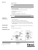
Electrical Connections: 18" (457 mm) leads on the coil. Threaded hole for 1/2" conduit.
Maximum Inlet Air Pressure: 40 psig (276 kPa). Clean, dry, oil free air is required
(reference EN-123).
Air Connections: 1/8" NPT.
N.C., Normally closed, Port 2.
N.O., Normally open, Port 3.
COM, Common, Port 1.
Valve Outputs
Flow Capacity: 1.15 scfm (580 ml/sec) @15 psig (138 kPa) supply with 1 psig (6.9 kPa)
drop.
Environment
Ambient Temperature Limits:
Shipping, -40 to 150°F (-40 to 65°C).
Operating, 32 to 125°F (0 to 52°C).
Supply Air, 40 to 130°F (4 to 54°C).
Humidity: 5 to 95% RH, non-condensing.
Location: NEMA Types 1, 2, 3, 3S, 4, and 4X .
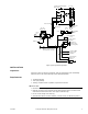
TYPICAL APPLICATION
When the supply fan is started, Electric Pneumatic (EP) Solenoid Air Valve E.P.-1 is ener-
gized, connecting N.C. and common ports. Main Air (20 Psig) is supplied to P.E.-1, starting
Humidifier Fan; to Room Humidistat H-1, placing normally-closed Steam Humidifier Valve
under control; to positioners of outside, Return and Relief Damper temperature controller,
and to Remote Exhaust Damper Motor M-4, opening the normally-closed Exhaust Damper
fully.
When the supply fan is stopped, E.P.-1 is de-energized, connecting the Common and N.O.
ports, exhausting main air from control devices. P.E.-1 stops the Humidifier Fan; the nor-
mally-closed Humidifier Valve closes; the Outside Air and Relief Damper close; the Return
Damper opens and the Exhaust Damper closes.
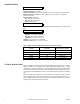
Table-1 Model Chart and Replacement Parts For Solenoid Air Valves.
Solenoid
Voltage
(AC 60 Hz)
Replacement Part Number
AL-150 24 PNR-326-24
AL-151 120 PNR-326-120
AL-152 208 PNR-326-208
AL-153 240 PNR-326-240
AL-155 480 PNR-326-480