
User Guide

F-24752-2 © Copyright 2008 TAC All Rights Reserved. 3
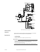
Figure-1 Typical Application Wiring Diagram.
INSTALLATION
Inspection
Inspect the carton for damage. If damaged, notify the appropriate carrier immediately.
Inspect the device for obvious damage. Return damaged products.
Requirements
• Job wiring diagrams
• Tools (not provided)
• Training: Installer must be a qualified, experienced technician
W
C A U T I O N
• Disconnect the power supply (line power) before installation to prevent equipment damage.
• Make all connections in accordance with the wiring diagram and in accordance with
national and local electrical codes.
Use copper conductors only.
• Do not exceed ratings of the device(s).
• Avoid locations where excessive moisture, corrosive fumes, or vibration is present.
To Relief (M )
Damper (N.C.)
8-13 psi
3
2
Branch (output) of mixed
air temperature controller
Port 3
N.O.
C
M
Typical Schematic Diagram
Motor Starter
L1 L2 L3
XI
A
I
H
Supply Fan
Motor
120V
H G
P.E
1
(N.O.)
Humidifier
Fan
Room Humidistat
(R.A.)
To N.C. Steam
Humidifier
Outside Air
Damper (N.C.)
3-8 psi (Typical)
H
1
M B
M
1
B
M S
M
4
Port 1
Common
Exhaust
Port 2
N.C.
M
20
AL-150
Bottom View
Red Leads
Green Lead
To Return (M )
Damper (N.O.)
Positioner
2