
User Guide

Copyright 2008, TAC
All brand names, trademarks and registered
trademarks are the property of their respective
owners. Information contained within this
document is subject to change without notice.
F-24752-2
www.tac.com
TAC
1354 Clifford Avenue
P.O. Box 2940
Loves Park, IL 61132-2940
Mounting
Remote Mounting
N O T E
This method requires the use of the enclosure on the coil. An integral mounting plate is
provided.
1. Fasten to wall or duct with two #8 sheet metal screws or equivalent.
2. Rotate the soleniod enclosure to position the wiring compartment, if necessary.
Inside Cabinet Mounting
1. Fasten to subpanel of cabinet with two #8 sheet metal screws.
2. Remove red cap.
3. Remove name plate by sliding out of coil.
4. Remove coil.
5. Install plunger tube through hole in electrical enclosure.
6. Re-install coil and coil hold down name plate snap red cap back on solenoid.
W
C A U T I O N
Do not over-tighten as this may cause distortion of plunger tube or damage coil.
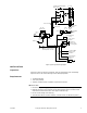
CHECKOUT
Go No Go Test
1. Connect solenoid ports.
2. Apply air to Port #1, Ports #1 and #3 should be connected.
3. Apply power to the solenoid, Ports #1 and #2 should be connected.
4. If Ports #1 and #2 are not connected, check to see if the proper voltage is applied.
5. Replace the solenoid with a functional unit if solenoid is powered and Ports #1 and #2
are not connected.
MAINTENANCE
Regular maintenance of the total system is recommended to assure sustained optimum
performance.
FIELD REPAIR
None. Replace with a functional solenoid.
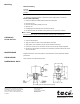
DIMENSIONAL DATA
Figure-2 AL-150 Dimensional Drawing.