
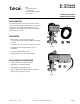
User Guide

2 © Copyright 2006 TAC All Rights Reserved. F-24748-1
SPECIFICATIONS
Valve Inputs Power Input: 6.5 Watts (energized).
Voltage: For available voltages, see Table-1.
Electrical Connections: 18” (457 mm) leads on the coil.
Maximum Inlet Air Pressure: 30 psig (207 kPa). Clean, dry, oil free air is required
(reference EN-123).
Air Connections: Three plastic ferrules included for plastic 1/4" tubing (PKG-1141).
N.C., Normally closed, port 1.
N.O., Normally open, port 2.
COM, Common, port 3.
Valve Outputs Flow Capacity: 0.3 scfm (142 ml/s) at 15 psig (103 kPa) supply with 1 psig (6.9 kPa) drop.
Environment Ambient Temperature Limits:
Shipping, -40 to 150°F (-40 to 65°C).
Operating, 40 to 130°F (4 to 54°C).
Supply Air, 40 to 130°F (4 to 54°C).
Humidity: 5 to 95% RH, non-condensing.
Location: NEMA Type 1.
Mounting: Vertical with solenoid at top (as shown).
ACCESSORIES None
TYPICAL APPLICATIONS
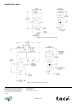
When power is supplied to the exhaust fan, the fan runs, and the solenoid air valve is
energized, closing port 2 and passing main air from port 1 through port 3 to damper actuator,
which opens the normally-closed exhaust damper.
When power is removed from the fan, the fan stops, and the solenoid air valve is de-
energized, closing port 1 and bleeding air from the damper actuator through port 3 and out
port 2 to atmosphere, closing the exhaust damper.
Figure 1 illustrates a typical application diagram for the AL-170 solenoid air valve.
Figure-1 Typical Application Diagram.
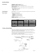
Solenoid
Voltage
(AC 60 Hz)
TAC Replacement Part
Numbers
Open Frame J-Box
AL-170 AL-180 24 PNR-325-24
AL-171 AL-181 120 PNR-325-120
N/A AL-182 208 PNR-325-208
N/A AL-183 240 PNR-325-240
N/A AL-185 480 PNR-325-480