
User Guide
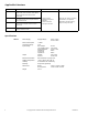

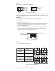
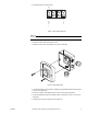
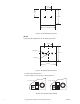
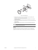
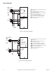
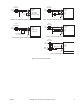
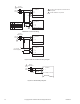
Table Of Contents
- Applications
- Features
- Applicable Literature
- F-26645
- MS40-7043Series, MS4x-7073 Series, MS4x-7153 Series DuraDrive Series Spring Return Proportional Actuator General Instructions
- F-27214
- MS41-6043, MS41-6083 Series DuraDrive Non-Spring Return Direct Coupled Actuator General instructions
- F-26748
- MS40-717x Series DuraDrive Series Spring Return Direct Coupled Actuator General instructions
- F-26646
- Mx4x-6xxx, Mx4x-7xxx Series DuraDrive Actuator Selection Guide
- AM-703
- Power Supply
- Supply Voltage:
- 24 Vac ± 15%
- 24 Vdc ± 15%
- Power Consumption
- <1 Watt
- Transformer Sizing
- 1 VA
- Input Voltage:
- Max voltage:
- zero (starting point)
- Span adjustment:
- Impedence:
- 0 to 20 mA
- Impedence:
- 25 Vdc
- 0 to 18 Vdc
- 2.6 to 17 Vdc
- 400 W
- 500 W
- Output
- Voltage:
- Current:
- 2 to 10 Vdc
- 15 mA max
- Electrical Connection
- Wire terminals, 14 gauge max.
- Ambient temperature
- -20 F to 150°F (-30 to 65° C)
- Humidity
- 5 to 95% RH non-condensing
- Mounting
- Snap-Track (provided)
- Dimensions
- Board:
- W/ snap-track
- 1-3/16” x 2-3/16” x 9/16”
- 1-7/8” x 2-3/8” x 15/16”
- Weight
- 0.9 oz.
- AM-704
- Power Supply
- Supply Voltage:
- 24 Vac ± 15%
- 24 Vdc ± 15%
- Power Consumption
- <1 Watt
- Transformer Sizing
- 2 VA
- Input
- -Isolation
- -Type
- -Trigger level
- -time between trigger pulses
- -Impedance
- -Pulse duration/resolution
- -Range 1
- -Range 2
- -Range 3
- -Range 4
- Optically isolated (when wired as such)
- Normal or triac, jumper selectable
- 12 to 24 Vac/Vdc or dry contact to com
- 12.5 milliseconds minimum
- Vac - 500 W, Vdc - 10 W
- Four selectable ranges, in seconds or dry contact or SSR closure ± 40% of signal increment
- 0.0235 to 6 seconds/in 0.0235 sec increments
- 0.0196 to 5 seconds in 0.0196 sec increments
- 0.1 to 25.5 seconds/ in 0.100 sec increments
- 0.59 to 2.93 seconds/ in 0.0092 sec increments
- Output
- Voltage:
- Current:
- Accuracy:
- 2 to 10 Vdc
- 15 mA max
- ± 2%
- Electrical Connection
- Wire terminals, 14 gauge max.
- Ambient temperature
- -20 to 150°F (-30 to 65° C)
- Operating Humidity
- 5 to 95% RH non-condensing
- Mounting
- Snap-Track (provided)
- Dimensions
- Board:
- W/ snap-track
- 2-3/16” x 2-3/16” x 9/16”
- 2-3/8” x 2-1/4” x 15/16”
- Weight
- 1.5 oz.
- AM-705, AM-706
- Power Supply
- 24 Vac ± 20%, 50/60 Hz, 24 Vdc ± 10%
- Transformer Sizing
- 1 VA
- Control Signal Y
- 0 to 10 Vdc, 2 to 10 Vdc (switchable)
- Power Output
- Up to 10 actuators (1 mA max)
- Degree of Protection
- AM-705 only NEMA 4 (IP54)
- Connection
- Terminals (14 gauge wire max)
- Humidity
- 5 to 95% RH non-condensing
- AM-708
- Resistance
- 500 W
- Length
- 9"
- Installation
- Figure-1 Jumper Settings.
- 1. Attach a variable signal source to the AM-703 input and power wires.
- 2. Apply power.
- 3. Input the minimum signal level.
- 4. Adjust the offset potentiometer to produce a 2 Vdc signal at the output. A clockwise rotation of the potentiometer screw will increase the output signal. See Figure-2.
- 5. Input the maximum signal level.
- 6. Adjust the span adjustment to produce a 10 Vdc signal at the output. A clockwise rotation of the potentiometer screw will increase the output signal. See Figure-2.
- 7. Double check the input-output calibration and install.
- Figure-2 Calibration Adjustments.
- Figure-3 Timing Jumper Settings.
- Figure-4 Input Jumper Settings.
- Figure-5 AM-705 Mounting.
- 3. Use two mounting screws (customer supplied) and appropriate drill to drill and mount the rear cover (Figure-6).
- 4. Punch out a plug to route wiring into box. Two screw-in caps are provided.
- 5. Connect wires (Figure-13) and set output switch to either 2 to 10 Vdc or 0 to 10 Vdc (Figure-8).
- 6. Secure front cover with screws removed in step one.
- Figure-6 AM-705 Mounting Dimensions.
- Figure-7 AM-706 Mounting Dimensions.
- Figure-8 AM-706 Output Switch Settings.
- Figure-9 AM-706 Mounting.
- 3. Rotate the dial until the percent sign is at the bottom. Pry the dial out with a flat screwdriver. A slot at the top of the dial is provided.
- 4. Remove the two screws from the front cover plate and separate the cover from the circuit board (Figure-9).
- 5. Position the circuit board behind the mounting surface. The wire screw terminals should be at the bottom.
- 6. Position the front cover plate and secure it to the circuit board with the two screws removed in step 4.
- 7. Connect wires (Figure-13).
- Figure-1 Jumper Settings.
- Wiring Diagrams
- Dimensions
- Installation

F-26895-4 © Copyright 2010 Schneider Electric All Rights Reserved. 5
2. Set input jumper for normal or triac.
N O T E
Do not move the adjustment screws for zero and span.
AM-705
1. Remove the two screws from the front cover.
2. Remove the front cover and position rear cover for mounting.
3. Use two mounting screws (customer supplied) and appropriate drill to drill and mount
the rear cover (Figure-6).
4. Punch out a plug to route wiring into box. Two screw-in caps are provided.
5. Connect wires (Figure-13) and set output switch to either 2 to 10 Vdc or 0 to 10 Vdc
(Figure-8).
6. Secure front cover with screws removed in step one.
N
O
R
M
A
L
T
R
I
A
C
P
2
Figure-4 Input Jumper Settings.
100
80
60
40
20
0
BELIMO
Figure-5 AM-705 Mounting.