
User Guide
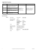

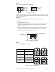
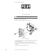
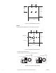
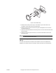
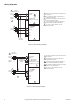
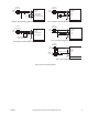
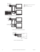
Table Of Contents
- Applications
- Features
- Applicable Literature
- F-26645
- MS40-7043Series, MS4x-7073 Series, MS4x-7153 Series DuraDrive Series Spring Return Proportional Actuator General Instructions
- F-27214
- MS41-6043, MS41-6083 Series DuraDrive Non-Spring Return Direct Coupled Actuator General instructions
- F-26748
- MS40-717x Series DuraDrive Series Spring Return Direct Coupled Actuator General instructions
- F-26646
- Mx4x-6xxx, Mx4x-7xxx Series DuraDrive Actuator Selection Guide
- AM-703
- Power Supply
- Supply Voltage:
- 24 Vac ± 15%
- 24 Vdc ± 15%
- Power Consumption
- <1 Watt
- Transformer Sizing
- 1 VA
- Input Voltage:
- Max voltage:
- zero (starting point)
- Span adjustment:
- Impedence:
- 0 to 20 mA
- Impedence:
- 25 Vdc
- 0 to 18 Vdc
- 2.6 to 17 Vdc
- 400 W
- 500 W
- Output
- Voltage:
- Current:
- 2 to 10 Vdc
- 15 mA max
- Electrical Connection
- Wire terminals, 14 gauge max.
- Ambient temperature
- -20 F to 150°F (-30 to 65° C)
- Humidity
- 5 to 95% RH non-condensing
- Mounting
- Snap-Track (provided)
- Dimensions
- Board:
- W/ snap-track
- 1-3/16” x 2-3/16” x 9/16”
- 1-7/8” x 2-3/8” x 15/16”
- Weight
- 0.9 oz.
- AM-704
- Power Supply
- Supply Voltage:
- 24 Vac ± 15%
- 24 Vdc ± 15%
- Power Consumption
- <1 Watt
- Transformer Sizing
- 2 VA
- Input
- -Isolation
- -Type
- -Trigger level
- -time between trigger pulses
- -Impedance
- -Pulse duration/resolution
- -Range 1
- -Range 2
- -Range 3
- -Range 4
- Optically isolated (when wired as such)
- Normal or triac, jumper selectable
- 12 to 24 Vac/Vdc or dry contact to com
- 12.5 milliseconds minimum
- Vac - 500 W, Vdc - 10 W
- Four selectable ranges, in seconds or dry contact or SSR closure ± 40% of signal increment
- 0.0235 to 6 seconds/in 0.0235 sec increments
- 0.0196 to 5 seconds in 0.0196 sec increments
- 0.1 to 25.5 seconds/ in 0.100 sec increments
- 0.59 to 2.93 seconds/ in 0.0092 sec increments
- Output
- Voltage:
- Current:
- Accuracy:
- 2 to 10 Vdc
- 15 mA max
- ± 2%
- Electrical Connection
- Wire terminals, 14 gauge max.
- Ambient temperature
- -20 to 150°F (-30 to 65° C)
- Operating Humidity
- 5 to 95% RH non-condensing
- Mounting
- Snap-Track (provided)
- Dimensions
- Board:
- W/ snap-track
- 2-3/16” x 2-3/16” x 9/16”
- 2-3/8” x 2-1/4” x 15/16”
- Weight
- 1.5 oz.
- AM-705, AM-706
- Power Supply
- 24 Vac ± 20%, 50/60 Hz, 24 Vdc ± 10%
- Transformer Sizing
- 1 VA
- Control Signal Y
- 0 to 10 Vdc, 2 to 10 Vdc (switchable)
- Power Output
- Up to 10 actuators (1 mA max)
- Degree of Protection
- AM-705 only NEMA 4 (IP54)
- Connection
- Terminals (14 gauge wire max)
- Humidity
- 5 to 95% RH non-condensing
- AM-708
- Resistance
- 500 W
- Length
- 9"
- Installation
- Figure-1 Jumper Settings.
- 1. Attach a variable signal source to the AM-703 input and power wires.
- 2. Apply power.
- 3. Input the minimum signal level.
- 4. Adjust the offset potentiometer to produce a 2 Vdc signal at the output. A clockwise rotation of the potentiometer screw will increase the output signal. See Figure-2.
- 5. Input the maximum signal level.
- 6. Adjust the span adjustment to produce a 10 Vdc signal at the output. A clockwise rotation of the potentiometer screw will increase the output signal. See Figure-2.
- 7. Double check the input-output calibration and install.
- Figure-2 Calibration Adjustments.
- Figure-3 Timing Jumper Settings.
- Figure-4 Input Jumper Settings.
- Figure-5 AM-705 Mounting.
- 3. Use two mounting screws (customer supplied) and appropriate drill to drill and mount the rear cover (Figure-6).
- 4. Punch out a plug to route wiring into box. Two screw-in caps are provided.
- 5. Connect wires (Figure-13) and set output switch to either 2 to 10 Vdc or 0 to 10 Vdc (Figure-8).
- 6. Secure front cover with screws removed in step one.
- Figure-6 AM-705 Mounting Dimensions.
- Figure-7 AM-706 Mounting Dimensions.
- Figure-8 AM-706 Output Switch Settings.
- Figure-9 AM-706 Mounting.
- 3. Rotate the dial until the percent sign is at the bottom. Pry the dial out with a flat screwdriver. A slot at the top of the dial is provided.
- 4. Remove the two screws from the front cover plate and separate the cover from the circuit board (Figure-9).
- 5. Position the circuit board behind the mounting surface. The wire screw terminals should be at the bottom.
- 6. Position the front cover plate and secure it to the circuit board with the two screws removed in step 4.
- 7. Connect wires (Figure-13).
- Figure-1 Jumper Settings.
- Wiring Diagrams
- Dimensions
- Installation

6 © Copyright 2010 Schneider Electric All Rights Reserved. F-26895-4
AM-706
To mount the AM-706 positioner use the following dimensions:
1. Drill the three holes (Figure-7).
2. Set the output to 2 to 10 Vdc or 0 to 10 Vdc (Figure-8).
3 1/4 (83)
3 1/4 (83)
1 7/16
(37)
1.62
(41)
Figure-6 AM-705 Mounting Dimensions.
1/4 (6.4) Dia.
.136 (3.4) Dia.
1 7/8 (48)
1 7/8 (48)
1.10 (28)
Figure-7 AM-706 Mounting Dimensions.
Y = 2 to 10 Vdc Y = 0 to 10 Vdc
Figure-8 AM-706 Output Switch Settings.