
User Guide

8 © Copyright 2008 TAC All Rights Reserved. F-24376-8
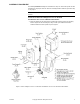
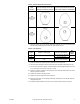
AV-395 or AV-396 on Obsolete 2-1/2" to 4" VB-9X13 Valve Bodies
See Figure-4 and YBA-651-1 & YBA-652, Valve Packing Kits General Instructions,
F-24185 for details.
Caution:
Before the packing nut is removed, the system pressure on the valve must be
reduced to zero (0) psig. If the packing nut is removed while there is pressure on the valve,
the packing can blow out of the valve.
1. Mount the bracket onto the valve body as follows:
a. Remove the packing nut and the bracket nut.
b. Place the bracket onto the valve body.
c. Replace and tighten the valve bracket nut.
d. Replace the packing nut.
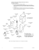
Figure-4 Valve Linkage for Obsolete 2-1/2" to 4" VB-9X13 Valve Bodies.
The following steps are common to all AV-390 valve linkages. Proceed with step 2 after
completing step 1 for the selected linkage.
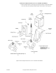
2. Thread the stem lock nut and stem extension down fully onto the valve stem.
3. Place the actuator onto the mounting bracket. Fasten the actuator to the mounting
bracket with the three 1/4 - 20 screws. Do not tighten the screws.
4. Place the nylon bushing onto the actuator shaft. (MA-31X and MA-41X actuators
require that a “C” ring be installed into the groove on the actuator shaft before placing
the nylon bushing onto the shaft.)
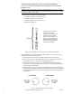
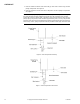
5. Position the actuator to the 3:00 (CW) or 9:00 (CCW) position so that the plunger cam
is pointing down. Use Figure-5 and Table-4Table-5 to determine whether the 3:00 (CW)
or 9:00 (CCW) position is the correct one for the plunger cam to be pointing down for
the application.
Figure-5 Actuator Shaft Position (Front View).
If any of the old style packing
components (no longer
available) require replacement,
replace the entire assembly
with the current YBA-652. The
old style bonnet assembly can
easily be identified by noting the
large hex head packing gland
nut with internal threads.