
User Guide

F-24376-8 © Copyright 2008 TAC All Rights Reserved. 9
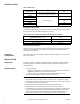
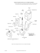
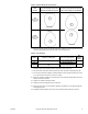
Table-5 Actuator Shaft and Cam Position.
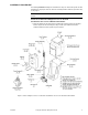
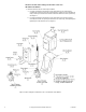
6. Place the plunger cam in the plunger and slip the plunger cam onto the actuator shaft
with the cam pointing down. Consult Table-6 for the proper cam.
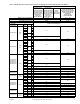
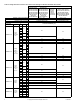
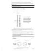
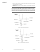
Table-6 Cam Selection.
7. Push the valve stem completely down against the lower valve seat.
8. Screw the stem extension until the holes in the stem extension and plunger line up.
9. Turn the stem extension upward, counterclockwise, into the plunger 2 full turns for 1/2"
to 2" valves and 1-1/2 turns for 2-1/2" to 4" valves.
10. Raise the actuator up until the connecting pin can be inserted through the holes in the
plunger and stem extension.
11. Tighten the actuator mounting screws.
12. Tighten the lock nut against the stem extension.
13. Place the front cover over the plunger assembly and fasten it to the actuator with two
self-tapping screws.
14. Install the position indicator to the end of the actuator shaft, pointing to “Closed”.
Actuator
Shaft
Position
Standard Factory Positions of Cam
except for Normally Closed Valves
w/MA-3XX and MA-4XX Actuators
Optional Cam Position Used to Reverse
Control Action (Standard for Normally
Closed Valves w/MA-3XX and MA-4XX)
CW
Short tooth on
actuator shaft
at 9:00
CCW
Short tooth on
actuator shaft
at 3:00
Cam Down
Cam Up
Cam Up
Cam Down
Use Cam
Marked
Included in Linkage Kits For These Valve Bodies
With
Nominal
Stroke
“7”
AV-91, AV-391, AV-93, AV-393
1/2" to 1-1/4" Obs. VB-9XXX
1/2"
“77” 1/2" to 2" VB-7XXX
“44-2”
AV-92, AV-392, AV-394, AV-395, AV-
396
2-1/2" to 4" VB-9XXX
1-1/2" & 2" Obs. VB-9XXX
1"