
Product Overview


F-23936-3 © Copyright 2008 TAC All Rights Reserved. 3
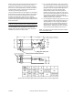
POSITIVE POSITIONER ADJUSTMENT
See Figure-1.
Span
The signal pressure change required to produce full actuator
stroke is determined by the feedback spring. Cataloged
models are supplied with factory installed 5 psi springs.
M556-14 is also supplied with a 10 psi spring attached to the
feedback arm.
Start Point
The signal pressure at which the actuator shaft begins to
move is adjustable 3 to 12 psig by rotating the recessed brass
knurled dial in the center of positioner.
The start point of the actuator may be adjusted by setting the
signal pressure to the desired value and turning the recessed
knurled wheel by hand until the actuator shaft begins to move.
Turning the wheel outward (toward the spring) raises the start
point.
the positioner requires a signal connection to “S” and a main
air connection to “M”. The positioner output, located above the
needle valve, is connected to the actuator signal port.
Adjustable Needle-Valve
Needle-valve allows the adjustment of the rate of actuator
movement.
With this needle-valve, 3", 4" and 6" actuators may be
adjusted with a small blade screw driver, if required, to:
Give the actuators the same relative rate of movement.
This makes it possible, for example, to have outside, return
and relief damper on an air handling unit move “together”,
rather that at different rates. This is especially important -
• When large air handling units are started and
stopped.
• When the dampers are switched from “summer” to
“winter” operation (or vice versa).
Both of the above examples can cause large damper
movements.
A narrower controller throttling range frequently can be
used if the actuators are adjusted to move slowly.
This is important for -
• Controlling supply air static pressure with a vortex
damper.
• Controlling mixed air temperature with outside, return
and relief dampers.
• Controlling space static pressure with one or more
relief dampers.
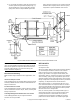
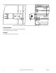
MOUNTING INSTRUCTIONS
M556
External Mounting
See Figure-2.
Whenever feasible, an M556 piston actuator operating an air
control damper should be mounted external to a duct by
means of its standard swivel post and plate. If necessary, the
mounting surface should be reinforced to withstand the stroke
force of more than 700 pounds that the M556 can exert.
When ordered properly, a control damper will have one or
more shaft extensions for the required number of actuators.
These extensions will be in their retracted or “stored” positions
when shipped and must be extended and locked in position
with their set screws or through bolts.
Before the actuator is mounted, the effective length of its
threaded crank arm should be adjusted to provide the
required damper rotation for full stroke (See table in Figure-2).
In addition, the “normal” position of the damper blades (open
or closed when signal air is removed and the actuator piston
retracts) and direction of shaft rotation as the piston is
extended must be determined to establish the orientation of
the actuator. If this orientation causes the positioner (when
furnished) to be located on the same side of the actuator as
the crank arm, there may be interference between the crank
arm and the feedback arm during operation. In this event, the
relationship between the mounting plate and the positioner
should be reversed by temporarily disconnecting the factory
tubing connection, swinging the mounting post 180° with
respect to the actuator housing and then re-connecting the
tubing.
After the above steps have been completed, the crank arm
clevis can be slipped onto the damper shaft extension without
clamping and the position of the mounting plate can be
determined by forming a right triangle (See Figure-2), with the
hypotenuse being the “effective length” of the threaded crank
arm and the base (along the centerline of the actuator) being
one-half of the actuator stroke (3", 76 mm). The mounting
plate can then be attached to the duct with suitable fasteners,
using care not to obstruct the movement of the damper
blades.
Note:
Note that the actuator need not be mounted at a right
angle to the damper frame.
The final installation step of locking the crank arm to the
damper shaft extension should be done when control ar is
available or by means of a squeeze bulb:
a. For a normally closed damper, apply air pressure to
the actuator equal to the low end of its spring range,
e.g.: 8 psig (55 kPa) for an 8 to 13 psig (55 to 90 kPa)
spring, then close the damper blades against their
stops; a slot in the end of the extension shaft
indicates blade position. After assuring that it is
parallel to the duct surface, clamp the crank arm to
the extension shaft by tightening the outermost crank
arm nut. When air pressure is removed from the
actuator, its residual low end spring force will provide
additional damper close-off pressure.