
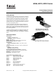
Product Overview


4 © Copyright 2008 TAC All Rights Reserved. F-23936-3
b. For a normally open damper, apply air pressure to the
actuator equal to the high end of its spring range, e.g.:
13 psig (90 kPa) for an 8 to 13 psig (55 to 90 kPa)
spring, then close the damper blades against their
stops. Clamp the crank arm to the extension shaft as
described above. Signal pressure above the spring
range will then provide additional close-off force.
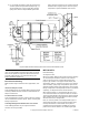
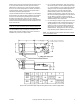
Figure-2 M556 Actuator Mounting Dimensions & External Installation Detail.
Note:
If an actuator is furnished with a positive positioning
relay, the final installation steps described above should be
done with the positioner’s output line disconnected and the
signal air applied directly to the actuator housing. (See
Positive Positioner Adjustment.)
Miscellaneous Mounting
M556 actuators may be utilized for other applications, such
as:
Internal Air Damper Control
These applications are non-standard. When required, internal
mounting of M556 actuators should be coordinated with the
damper manufacturer.
Fan Scroll Inlet Van Control
These field applications must be custom-engineered, utilizing
the fan manufacturer’s data for torque, stroke, mounting and
linkage requirements.
Centrifugal Refrigeration Machine Inlet Vane Control
These OEM applications are pre-engineered and the
actuators are factory installed.
M573 & M574
External Mounting
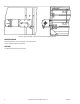
See Figures 3 and 4
Whenever feasible, M573 or M574 piston actuators operating
air control dampers should be mounted on the external
surface of ducts by means of right angle brackets (See
Figure-4). By selection of the proper model number (See
Specification Table-1), actuators of the proper size (effective
area and stroke), spring range and positioner option can be
obtained complete with the right angle bracket. the necessary
linkage components for driving damper shafts are purchased
separately, see Replacement Part and Accessories.
When ordered properly, a control damper will have one or
more shaft extensions for the required number of actuators.
These extensions will be in their retracted or “stored” positions
when shipped and must be extended and locked in position
with their set screws or through bolts.
Next, the “normal” position of the damper blades (open or
closed when signal air is removed and the actuator piston
retracts) and direction of shaft rotation as the piston is
extended must be determined to establish the mounting
position of the actuator bracket. The standard right angle