
Product Overview


F-23936-3 © Copyright 2008 TAC All Rights Reserved. 5
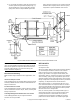
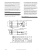
bracket has two (2) locator holes (dimension E in Figure-3) for
3" (76 mm) stroke actuators and two (2) locator notches
(dimension F in Figure-3) for 4" (102 mm) stroke actuators;
the choice of a locator being based on whether clockwise or
counterclockwise rotation is required as the piston shaft is
extended by increasing signal pressure.
The pre-assembled crank arm is then slipped over the damper
shaft extension and, when properly positioned, the bracket is
secured to the duct surface by driving sheet metal screws
through its mounting holes, using care not to obstruct
movement of the damper blades. If the duct is to be insulated,
suitable standoff posts and bolts should be substituted for the
sheet metal screws.
Note:
3" stroke actuators use the middle pivot hole of the
crank arm; 4" stroke actuators use the outermost pivot hole.
The final installation step of locking the crank arm to the
damper shaft extension should be done when control air is
available or by means of a squeeze bulb:
a. For a normally closed damper, apply air pressure to
the actuator equal to the low end of its spring range,
e.g.: 5 psig (34 kPa) for a 5 to 10 psig (34 to 69 kPa)
spring, then close the damper blades against their
stops; a slot in the end of the extension shaft
indicates blade position. After assuring that it is
parallel to the duct surface, clamp the crank arm to
the extension shaft by tightening the two (2) hexhead
screws. When air pressure is removed from the
actuator, its residual low end spring force will provide
additional damper close-off pressure.
b. For a normally open damper, apply air pressure to the
actuator equal to the high end of its spring range, e.g.:
10 psig (69 kPa) for a 5 to 10 psig (34 to 69 kPa)
spring, then close the damper blades against their
stops. Secure the crank arm to the drive shaft as
described above. Signal pressure above the spring
range will then provide additional close-off force.
Note:
The standard actuator hardware will rotate a damper
90° for full actuator stroke.
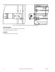
Figure-3 M573 and M574 Right Angle Mounting Dimensions for External Applications.