
Product Overview
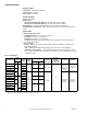
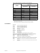
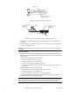
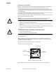
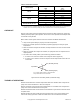
Table Of Contents

10 © Copyright 2007 TAC All Rights Reserved. F-06491-28
Table-3 Power Wire Selection.
CHECKOUT
After the entire system has been installed and the actuator has been powered up, perform the
following check for proper system operation. Check for the correct operation of the damper while
the actuator is being stroked.
Note: Smoke control systems must be tested in accordance with NFPA Standard 92A.
1. Verify that the system wiring is properly connected and powered.
2. Be sure the controller (manual or automatic) is operating properly according to system
requirements.
3. When the controller energizes the actuator, the output shaft must run to the end of the stroke
(180° CW).
4. When the controller de-energizes the actuator, the spring will return the output shaft to its
original position.
5. The action of the auxiliary switch (-500 models only) shall be as follows:
a. C makes to N.C. when the actuator is de-energized. Refer to (Figure-8).
b. C makes to N.O. when the actuator is energized and the output shaft reaches the end
of the stroke.
Figure-8 Action of Auxiliary Switch (-500 Models Only).
THEORY OF OPERATION
MA-305 and MA-405 series actuator output shafts rotate 180° clockwise when energized and
spring return counterclockwise to 0° when de-energized.
MA-31x and MA-41x series actuator output shafts rotate 170° clockwise when energized and
spring return counterclockwise when de-energized.
MA-305 and MA-405 series actuator motors are assembled to a gear train and stall at the end of
the power stroke.
MA-318, MA-416, MA-418, and MA-419 series actuators have an end of travel switch which
reduces the running input from 70 watts to 25 watts at the end of clockwise shaft rotation.
Actuator Series
Wire Size
AWG
Maximum Run
a b
ft (m)
MA-305
14 122 (37)
12 191 (58)
10 305 (93)
MA-405 14 2800 (853)
MA-318
14 44 (13)
12 68 (21)
10 110 (34)
MA-416, MA-418, MA-419
14 950 (290)
12 1580 (482)
a Each run has two wires.
b The length given is for a maximum two-wire run, for one actuator. When multiple actuators are used, determine the
maximum run for each actuator by dividing the number of actuators into the corresponding maximum run.
N.C. (Normally Closed)
N.O. (Normally Open)
C (Common)
N.O. makes when actuator is energized and
output shaft reaches end of stroke.