
Product Overview
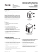
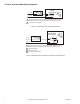
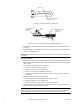
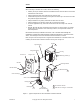
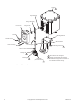
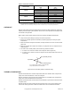
Table Of Contents

F-06491-28 © Copyright 2007 TAC All Rights Reserved. 5
INSTALLATION
Inspection Inspect the package for damage. If damaged, notify the appropriate carrier immediately.
If undamaged, open the package and inspect the device for obvious damage. Return damaged
products.
Requirements • Job wiring diagrams
• Tools (not provided):
– Digital Volt-ohm Meter (DVM)
– Appropriate screwdriver(s) for cover and mounting screws
– Appropriate drill and drill bit for mounting screws
– Appropriate wrenches for adjustment of damper and valve linkages
• Appropriate accessories
• Mounting screws (not provided)
• Training: Installer must be a qualified, experienced technician
Warning:
• Disconnect the power supply (line power) before installation to prevent electrical shock and
equipment damage.
• Make all connections in accordance with the wiring diagram and in accordance with
national and local electrical codes. Use copper conductors only.
Caution:
• Do not apply power to the unit unless the damper linkage and/or the valve assembly have
been installed.
• Avoid locations where excessive oil, dust, moisture, corrosive fumes or vibration, or an
explosive atmosphere is present. The actuator case is intended primarily to provide a
degree of protection against windblown dust, rain, sleet, and external ice formation (NEMA
Type 4).
Mounting Mount the actuator according to the following requirements:
1. Allow a minimum of 6
" (152 mm) clearance behind the actuator for access to the wiring
compartment.
2. Locate the actuator in a weather-protected area.
3. To ensure water and weather resistance, install the cover gasket (provided) and use
water-tight conduit fittings.
Dampers
Install the actuator and the damper linkage, so that 180° of actuator shaft rotation drives 90° of
damper shaft rotation, as follows:
Actuator Mounting and Damper Linkage Installation
1. Mount the actuator in an appropriate position near the damper.
Note:
• MA-305 and MA-405 series actuators are not position-sensitive, and in damper applications,
may be mounted in any position. However, the upright position is preferred.
• MA-318, MA-416, MA-418, and MA-419 series actuators must be mounted so that the
output shaft lies in a horizontal position.
• To the extent possible, position the actuator to optimize the length of the damper rod
needed to link it with the damper. A damper rod that is too long is not rigid enough for good
control, and a damper rod that is too short makes it difficult to adjust the linkage.
2. Install crank arms onto the driven shaft and the actuator shaft. Tighten the crank arm on the
driven shaft. Do not tighten the crank arm on the actuator shaft at this time.
3. Install a linkage connector onto the actuator shaft crank arm, at the prick point. Refer to
(Figure-3) and (Figure-4).