
Product Overview
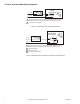
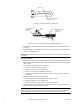
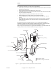
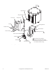
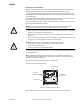
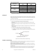
Table Of Contents

6 © Copyright 2007 TAC All Rights Reserved. F-06491-28
Figure-3 Location of Prick Point on Crank Arm.
Figure-4 180° Actuator Rotation Driving a Damper Rotation of 90°.
4. Install a linkage connector onto the driven shaft crank arm, at the end of the slot. Refer to
(Figure-4).
5. Install the damper rod in the linkage connectors on both crank arms and tighten the linkage
connector screws finger-tight.
Caution: Never attempt to turn the actuator shaft with a wrench or a crank; this may damage
the actuator.
Linkage Adjustment
1. Verify that the crank arm on the actuator shaft is loose. Rotate, by hand, the crank arm on
the actuator to drive the linkage and the damper shaft through its full stroke, to ensure proper
damper action.
2. For normally closed dampers, proceed as follows:
a. Return the damper to the closed position.
b. Tighten the crank arm on the actuator shaft.
c. Loosen the screw on one of the linkage connectors.
d. While pushing the damper closed, tighten the linkage connector screws to secure the
damper rod.
3. For normally open dampers, proceed as follows:
a. Move the damper to approximately 85° of the full open position.
b. Tighten the crank arm on the actuator shaft.
c. Tighten the linkage connector screws to secure the damper rod.
4. Run the actuator back and forth through its full stroke and check for proper damper and
linkage operation. Adjust the linkage if required.
Caution: When linking an actuator to a damper, be sure that it can complete its full stroke. If
the damper stops the actuator before it has reached its electrical limit of travel on the power
stroke, the actuator may be permanently damaged. Readjust the linkage as necessary.
Prick Point
123
Slot provides adjustment
from 7/8" to 3-1/8".
Actuator
Shaft
0°
0°
90°
180°
Install Connector at
Prick-Point on
Crank Arm
Driven
Shaft
Install Connector at
End of Slot on
Crank Arm