
Product Overview
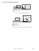
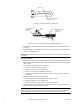
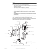
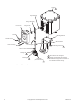
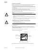
Table Of Contents

F-06491-28 © Copyright 2007 TAC All Rights Reserved. 7
Valves
Note:
When mounting an actuator onto a valve, observe the following:
• Allow 3" (76 mm) of clearance above the assembled actuator and valve for the removal and
reattachment of the actuator.
• Always install single-seat valves with pressure under the seat.
• Install all two-way valves so that they close against the flow. A tag or an arrow on the valve
body indicates proper flow direction.
• Always install three-way mixing valves with two inlets and one outlet.
• Always install three-way diverting valves with one inlet and two outlets.
• For steam applications only, mount the actuator above the valve body at 45° from the
vertical.
• MA-318, MA-416, MA-418, and MA-419 series actuators can be mounted in any upright
position above the centerline of the valve body. However, the output shaft must lie in a
horizontal position.
For detailed valve linkage installation instructions, refer to
AV-29x Valve Linkage for
Hazardous Location Gear Train Actuators General Instructions, F-27441 or
AV-390
Series, Valve Linkage for Gear Train Actuators General Instructions, F-24376.
Refer to Figure-5 for the components of a typical valve installation of a standard actuator. For
installing an actuator with a hazardous location housing, refer to Figure-6.
Figure-5 Typical Components for Valve Installation of Standard Actuator.
Indicator Screw
Front Cover
Nylon Bushing
Actuator
Mounting Screws (3)
Mounting Bracket
Valve Body
(VB-7XXX Shown)
Plunger Assembly
Connecting Pin
Stem Extension
Stem Locknut
Packing Nut
Mounting Nut
Cover Screws (2)
Indicator
Plunger Cam
1
1
1
1
"C" Ring
1 Not included in AV Kits.
2 Used with 1/2" through 2" valve bodies.
2