
Product Overview
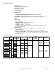
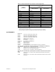
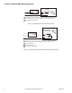
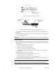
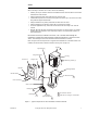
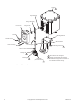
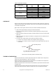
Table Of Contents

F-06491-28 © Copyright 2007 TAC All Rights Reserved. 9
WIRING
Hazardous Location Models
Make all electrical connections to the assembly in accordance with the job wiring diagram, the
National Electric Code Article 500, and in compliance with the local electrical codes.
Two 3/4" pipe tapped openings are provided in the housing for rigid conduit connections. It is
recommended to insert a chase nipple from inside of the housing to prevent threads from cutting
or damaging wiring.
When wiring, take care to lay all leads in the wiring channel located just under the housing cover
to protect the leads from any sharp edges which may be in the vicinity.
The housing and the edge of the cover are stamped with the letter "O." When replacing the cover,
the letters must be aligned with each other.
Warning: The cover-to-housing orientation must be maintained in order to preserve the
integrity of the seal. Failure to observe this warning can result in injury or death.
1. Remove twelve cover screws and cover. Place cover, machined surface up, in a protected
location to avoid damage to machined surfaces.
2. Make all wiring connections to actuator taking care to lay all leads in the wiring channel
provided.
3. Before enclosing the actuator, wipe machined surfaces of housing clean with a lint free cloth
and apply one of the UL approved compounds. See Note below.
Warning: Failure to observe these warnings can result in injury or death.
• Do not scrape, scratch, or use abrasives on the machined surfaces.
• Ensure the surfaces are clean.
• Use only the approved compounds listed below.
4. Secure cover tight against the enclosure in the same position before removal with the twelve
screws provided.
Note: Underwriters Laboratories has sanctioned the use of the following compounds on
hazardous location ground joints: Crouse-Hinds type OSL lubricant, Crouse-Hinds type STL
lubricant, or "No-OXID" oil, grade "D."
Two 1/2
" conduit knockouts are provided on the actuator case.
Refer to Figure-7 for terminal locations.
Figure-7 Actuator Terminal Locations.
Refer to Table-3 for the selection of the proper gage wire for the length of the wire run.
Feed-Through
Terminal Bloc
k
Case Ground
Power Terminals
A
ux. Switch
(-500 Models)
(Shown with Back Cover Removed)
N.O.
N.C.
C
L 1
L 2