
User Guide
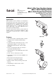
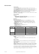
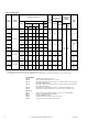


Table Of Contents
- Application
- Features
- . Two position models controlled by SPST controller
- . Floating models controlled by SPDT floating controllers
- . Proportional models controlled by 2-10 Vdc, or 4-20 mAdc with the addition of a 500 ohm resistor. Control function direct/reverse action is switch selectable
- . 220 lb force (979 newton) with 1/2” (13 mm) or 1" (25 mm) nominal linear stroke
- . Automatically sets control signal input span to match valve travel
- . 24 Vac, 120 Vac, and 230 Vac models
- . Rugged die-cast enclosures rated for NEMA 2, UL Type 2/IP54
- . Overload protection throughout stroke
- . Compact size for application flexibility
- . Manual override to allow positioning of valve and preload
- . Integral linkage for direct mount to valves
- . Five year warranty
- Applicable Literature
- SPECIFICATIONS
- TYPICAL TWO POSITION CONTROL (wiring diagrams)
- TYPICAL FLOATING CONTROL (wiring diagrams)
- TYPICAL PROPORTIONAL CONTROL (wiring diagrams)
- Figure-6 Typical Wiring Diagrams for Proportional Control 24 Vac Basic Models.
- Figure-7 Typical Wiring Diagrams for Proportional Control 24 Vac Models Wired in Parallel.
- INSTALLATION
- Caution:
- Mounting
- Table-2 Valve Configuration Chart.
- Figure-10 Mx51-720x Series Actuator Exploded View.
- Figure-11 Typical Assembly and Installation of Mx51 Series Actuator to 1-1/4" to 2" VB-7xxx Series Valve Bodies, Stem-Up Closed or Open, 2-Way and 3-Way Valves.
- Installation: Mx51-720x Series Actuator to 1-1/4" to 2" VB-7xxx Series Valve Bodies, Stem-Up Closed or Open, 2-Way and 3-Way
- A. Install the actuator onto the valve. Set up the assembly according to the numbered steps in Figure-11.
- 1. Locate the jam nut that came packaged with the actuator.
- 2. Screw the jam nut onto the valve stem all the way as far as it will go. You may need to use a 5/16" (Tool-20-1) open-end wrench. At least 1/2" of the valve stem threads should extend above the nut.
- 3. Place lock washer over valve stem.
- 4. Thread the stem extension onto the valve stem, making contact with the lock washer and jam nut.
- 5. Ensure 15° or 1-1/2 turns of manual override for actuator preload. See Figure-18.
- 6. Orient the actuator mounting bracket on the valve and tighten the mounting nut securely against the bracket using Tool-37. Raise the valve stem to the full up position.
- 7. Rotate stem extension until the through hole lines up with the through hole of actuator rack. Insert connecting pin to secure stem extension and tighten jam nut against stem extension using 5/16" (Tool-20-1) open end wrench.
- 8. Affix open/closed label to the indicator in the appropriate position.
- 9. Insert set screw (packaged with actuator) into the most accessible side. Tighten with size 10 IP Torx Plus bit to 20 - 25 lb-in (2.3 to 2.8 N-m).
- B. Apply power to the actuator and check the system operation for heating or cooling output in response to the control signal.
- Figure-12 Mx61-720x Series Actuator Exploded View.
- Installation: Mx51-720x Series Actuator to 1-1/4" to 2" VB-7xxx Series Valve Bodies, Stem-Up Closed or Open, 2-Way and 3-Way
- Figure-13 Typical Assembly and Installation.
- Installation: Mx61-720x Series Actuator to 2-1/2" to 4" VB-9xxx and 2-1/2" to 5" VB-8xxx Series Valve Bodies, Stem-Up Closed 2-Way and 3-Way
- A. Install the actuator onto the valve. Set up the assembly according to the numbered steps in Figure-13.
- 1. Locate the jam nut that came packaged with the actuator.
- 2. Screw the jam nut onto the valve stem all the way as far as it will go (you may need to use a 3/4" open-end wrench). At least 1/2" of the valve stem threads should extend above the nut. Place the lock washer over the valve stem.
- 3. Thread the stem extension onto the valve stem, making contact with the lock washer and jam nut.
- 4. Ensure 15° or 1-1/2 turns of manual override actuator preload. See Figure-18.
- 5. Orient the actuator mounting bracket on the valve, place lock washer over valve stem and tighten the mounting nut securely against the bracket using spanner wrench. Raise the valve stem to the full up position.
- 6. Rotate stem extension until the through hole lines up with the through hole of actuator rack. Insert connecting pin to secure stem extension and tighten jam nut against stem extension using 3/4" open end wrench.
- 7. Affix open/closed label to the indicator in the appropriate position.
- B. Apply power to the actuator and check the system operation for heating or cooling output in response to the control signal.
- Figure-14 Typical Assembly and Installation.
- Installation: Mx61-720x Series Actuator to 2-1/2" to 4" VB-9xxx Series and 2-1/2" to 5" VB-8xxx Valve Bodies, 2-Way Stem-Up Open
- A. Install the actuator onto the valve. Set up the assembly according to the numbered steps in Figure-14.
- 1. Locate the jam nut that came packaged with the actuator.
- 2. Screw the jam nut onto the valve stem all the way as far as it will go (you may need to use a 3/4" open-end wrench). At least 1/2" of the valve stem threads should extend above the nut. Place the lock washer over the valve stem.
- 3. Thread the stem extension onto the valve stem, making contact with the lock washer and jam nut.
- 4. Orient the actuator mounting bracket on the valve. Place lock washer over valve stem and tighten the mounting nut securely against the bracket using spanner wrench. Ensure the valve stem is completely pushed down.
- 5. Insert the hex wrench into manual override and crank to extend the actuator rack to its fully extended position, back off 1-1/2 turn, and lock (see Figure-18). Remove hex wrench to prevent accidental spring return of the actuator.
- 6. Rotate stem extension until the through hole lines up with the through hole of actuator rack. Insert connecting pin to secure the assembly. Tighten jam nut against stem extension using 3/4" open end wrench.
- 7. Affix open/closed label to the indicator in the appropriate position.
- B. Apply power to the actuator and check the system operation for heating or cooling output in response to the control signal.
- Installation: Mx61-720x Series Actuator to 2-1/2" to 4" VB-9xxx and 2-1/2" to 5" VB-8xxx Series Valve Bodies, Stem-Up Closed 2-Way and 3-Way
- Valve Mounting
- MANUAL OVERRIDE OPERATION

Printed in U.S.A. 11-06 © Copyright 2006 TAC All Rights Reserved. F-27120-4
TAC
1354 Clifford Avenue
P. O. Box 2940
Loves Park, IL 61132-2940
www.tac.com
Application
TAC DuraDrive
Linear Actuators are designed to
mount directly onto two-way or three-way valves. They
provide linear travel to economically operate 1-1/4" to
2" VB-7xxx, 2-1/2” to 5" VB-8xxx, 2-1/2" to 4" VB-931x,
and discontinued 1-1/2” to 4” VB-9xxx valves in hot
water, chilled water, and steam applications up to
366°F (186°C) fluid temperature.
The linear spring return actuators provide either two
position, floating or proportional modulation control
(depending on model selection) of valves in HVAC
systems.
Features
• Two position models controlled by SPST controller
• Floating models controlled by SPDT floating
controllers
• Proportional models controlled by 2-10 Vdc, or 4-20
mAdc with the addition of a 500 ohm resistor.
Control function direct/reverse action is switch
selectable
• 220 lb force (979 newton) with 1/2” (13 mm) or
1" (25 mm) nominal linear stroke
• Automatically sets control signal input span to match
valve travel
• 24 Vac, 120 Vac, and 230 Vac models
• Rugged die-cast enclosures rated for NEMA 2, UL
Type 2/IP54
• Overload protection throughout stroke
• Compact size for application flexibility
• Manual override to allow positioning of valve and
preload
• Integral linkage for direct mount to valves
• Five year warranty
MAx1-720x Two Position Series
MFx1-7203 Floating Series
MSx1-7203 Proportional Series
TAC DuraDrive™ Linear Series
Spring Return Actuator
General Instructions
Mx51-720x
Mx61-720x