
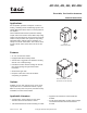
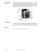
Product Overview

2 © Copyright 2008 TAC All Rights Reserved. F-08366-13
SPECIFICATIIONS
Control Circuit: Three Wire SPDT snap-acting switch or equivalent.
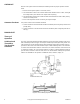
Shaft Rotation: Unidirectional clockwise 180° when power is applied.
Auxiliary Switch: Adjustable SPDT is standard. Factory set to make (or break) at mid stroke.
Running , 5.8A at 120 Vac, 2.9 at 240 Vac
Locked Rotor: 34.8 at 120 Vac, 17.4 at 240 Vac
Non-inductive, 12A at 120 Vac, 6 at 240 Vac.
Environment:
Ambient temperature limits: Shipping and storage -40 to 136 °F (-40 to 58 °C)
Operating -40 to 136 °F (-40 to 58 °C).
Humidity: 5 to 95% RH, non-condensing.
Locations: NEMA 1. Optional NEMA 4 with AM-363 gasket, or hazardous service locations
N.E.C., Class 1, Groups C and D, and Class 2, Groups E, F, and G.
Connections: Coded screw terminals.
Options: Hazardous locations specify MC6-351, 421, or 431 (60 hz), MC7-4311 (50 hz).
Agency Listing: UL File #E9429 standard models.
UL File #29291 Hazardous location models. Temperature code T6 for hazardous housing.
ACCESSORIES
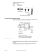
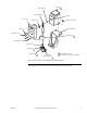
Damper Linkage Accessories (See Figure-1
AM-111 Crank arm for 5/16" diameter damper shaft
AM-112 Crank arm for 3/8" diameter damper shaft
AM-113 Crank arm for actuator or 1/2" diameter damper shaft
AM-115 Crank arm for 7/16" diameter damper shaft
AM-116 Splined crank arm for actuator
AM-122 Linkage connector straight type
AM-123 Damper clip
AM-125 5/16" diameter x 20" damper rod
AM-125-048 5/16" diameter x 48" damper rod
AM-132 Ball joint connector
AM-161 Damper linkage kit
AM-161-1 Damper linkage kit
AM-301 90 degree mounting bracket
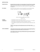
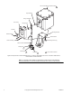
Valve Linkage Accessories (See Figure-4
AV-330 Valve linkage for 2-1/2" & 3" VB-9323
AV-352 Valve linkage for 2-1/2" to 6" VB-9213 or VB-9313 valve bodies and 4" to 6" for VB-9323
AV-393 Valve linkage for 1/2" to 1-1/4" VB-92x3 or VB-93x3
AV-394 Valve linkage for 1-1/2" & 2" VB-92x3 or VB-93x3
AV-396 Valve linkage for 2-1/2" to 4" VB-9213 or VB-9313
Valve Linkage Hazardous Location Accessories (See Figure-5
AV-293 Valve linkage for 1/2" to 2" VB-7xxx series for hazardous locations
AV-296 Valve linkage for 2-1/2" and 3" VB-9xxx (bronze) series for hazardous location
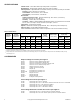
Table-1 Model Chart.
Part No.
Standard
Service
Part No.
Hazardous
Location
a
b
a
Class 1, Groups C & D, and Class 2, Groups E, F, and G hazardous locations; refer to EN-56-2, F-18451. Hazardous location valve actuators can also be used
for hazardous location damper applications.
b
Models for hazardous locations are only available as factory-built enclosure/actuator assemblies.
Input
No Load
Timing
(Sec./180
×)
Rated Torque
Lb.-in. (N-m)
Nominal Damper
c
Area
Sq. Ft. (m2)
c
Damper ratings are nominal and based on standard (not low leakage) dampers at 1" (25.4 mm) W.C. static pressure and 2000 FPM (10 ml/S) velocity.
Volts Hz Watts VA Rating
Parallel
Blade
Opposed
Blade
MC-351 MC6-351 24 60 28 53 70 220 (25) 122 (11) 157 (15)
MC-421 MC6-421 120 60 50 96 20 175 (20) 97 (9) 125 (12)
MC-431 MC6-431 120 60 50 96 30 220 (25) 122 (11) 157 (25)
MC-4311 — 240 60 50 96 30 220 (25) 122 (11) 157 (15)
MC5-4311
d
d
Not CSA approved.
MC7-4311
d
240 50 50 96 36 220 (25) 122 (11) 157 (15)