
Product Overview

4 © Copyright 2008 TAC All Rights Reserved. F-08366-13
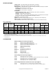
INSTALLATION
Requirements Preferred mounting for the actuator is in the upright position, but other positions are acceptable.
Adjustable speed units should never be mounted upside down or with the output shaft pointing
upward. Allow six inches clearance above the actuator wiring compartment. If an AM type
mounting bracket is not used, the base of the actuator may be used as a template for marking
mounting holes.
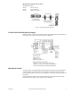
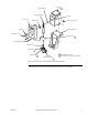
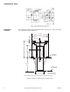
Procedure Actuator may be used in damper and valve control applications. Figure-3 illustrates linkage
operating an arm through a 90° arc. To fasten damper linkage proceed as follows.
Figure-3 180° Actuator Rotation Driving a Damper
Rotation of 90°.
Damper
Installation
1. Fasten linkage connector at end of damper crank arm.
2. Fasten linkage connector at punch mark on actuator crank arm (about .707 of the radius).
3. Move damper to normal position and clamp connecting link to connectors.
4. Check adjustment for proper operation by running actuator and driven shaft between limits
of travel.
Caution:
If crank arm does not provide proper travel, reset connecting link in linkage
connector. Never attempt to turn the actuator shaft with a wrench or a crank. This may damage
the gears.
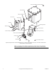
Valve Installation Install all valves with pressure under seat. Refer to flow arrow on body or piping information on
valve body tag. Three way mixing valves should be installed with two inlets and one outlet. Three
way diverting valves should be installed with one inlet and two outlets.
To assemble an actuator to a valve, refer to detailed instructions on
AV-3xx General Instruction
Sheet
, F-19068 or
AV-29x Series Hazardous Location Valve Linkage for Geartrain Actuators
General Instructions,
F-27441.