
Selection Guide
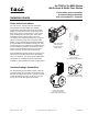
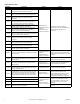
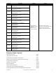
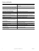
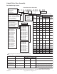
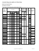
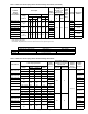

Table Of Contents
- Selection Guide Contents
- Features and Benefits
- Features
- Benefits
- Linked Globe Valve Assembly
- Actuator/Linkage Assemblies for Globe Valves
- System Design Considerations
- Installation Considerations
- Valve/Actuator Combinations
- Linked Globe Valve Assemblies Specifications
- Actuator Specifications and Valve Assembly Mounting Dimensions
- Actuator Specifications
- Dimensions - 1/2” to 2” Globe Valve Assemblies
- Actuator Specifications
- Dimensions - 1/2” to 2” Globe Valve Assemblies
- Dimensions - 2-1/2” and 3” Screwed Globe Valve Assemblies
- Dimensions - 2-1/2” to 4” Flanged Globe Valve Assemblies
- Actuator Specifications
- Dimensions - 5” and 6” Flanged Globe Valve Assemblies
- Actuator Specifications
- Dimensions - 1/2” to 2” Globe Valve Assemblies
- Actuator Specifications
- Dimensions - 1/2” to 2” Globe Valve Assemblies
- Dimensions - 2-1/2” and 3” Screwed Globe Valve Assemblies
- Dimensions - 2-1/2” to 6” Flanged Globe Valve Assemblies
- Actuator Specifications
- Dimensions - 1/2” to 2” Globe Valve Assemblies
- Dimensions - 2-1/2” and 3” Screwed Globe Valve Assemblies
- Dimensions - 2-1/2” to 6” Flanged Globe Valve Assemblies

F-26752-12 Copyright 2008 TAC All Rights Reserved. 5
Linked Globe Valve Assembly
Part Numbering System
Port Code
Control Signal Type
A = Two Position
F = Floating
S = Proportional
Configuration
721, 921 = 2-Way, Stem Up Open
722, 922 = 2-Way, Stem Up Closed
731, 931 = 3-Way, Mixing
732 = 3-Way, Diverting
Connection
1 = Union Straightway
3 = Threaded NPT (Bronze)
or Flanged (Cast Iron)
4 = Union Sweat End
5 = Metric Thread (Rp)
Pattern Code
4 = Straightway
(Bronze)
5 = Globe Flanged
(Cast Iron)
Linked Globe Valve Assemblies
Actuator
V X - X X X X - X X X - X - X X
Two Position
MA40-7043=536
MA40-7043-501=537
MA40-7040=532
MA40-7040-501=533
MA40-7041=534
MA40-7041-501=535
MA40-7173=576
MA40-7170=572
MA40-7171=574
MA41-7153=556
MA41-7153-502=557
MA41-7150=552
MA41-7150-502=553
MA41-7151=554
MA41-7151-502=555
MA41-7073=546
MA41-7073-502=547
MA41-7070=542
MA41-7070-502=543
MA41-7071=544
Floating
MF41-6043=505
MF41-6083=506
MF41-6153=508
MF41-6343=516
MF40-7043=536
MF40-7043-501=537
MF41-7073=546
MF41-7073-502=547
MF41-7153=556
MF41-7153-502=557
MF40-7173=576
1 The configuration of the valve assembly determines the valve stem
position and flow, as shipped from the factory. See the table below.
1
c
The actuator is factory mounted
with the "L" side facing up and the actuator rotation switch (if present) set to "L." The actuator rotates CW as the control signal
Proportional
MS41-6043=505
MS41-6083=506
MS41-6153=508
MS41-6343=516
MS40-7043=536
MS40-7043-501=537
MS40-7043-MP=538
MS40-7043-MP5=539
MS41-7073=546
MS41-7073-502=547
MS41-7153=556
MS41-7153-502=557
MS40-7173=576
MS40-7170=572
MS40-7171=574
Valve Assemblies Valve Body Action Factory Shipped Position
c
Action
c
Valve Stem Flow
VX-721X-XXX-4-P 2-Way Stem Up Open Up Open A to AB Flow decreases as actuator rotates CW
VX-921X-XXX-X-P
VX-722X-XXX-4-P 2-Way Stem Up Closed Up Closed A to AB Flow increases as actuator rotates CW
VX-922X-XXX-X-P
VX-731X-XXX-4-P 3-Way Mixing Up Flow B to AB A to AB Flow increases as actuator rotates CW
VX-931X-XXX-X-P B to AB Flow decreases as actuator rotates CW
VX-732X-XXX-4-P 3-Way Diverting Up Flow B to AB B to A Flow increases as actuator rotates CW
B to AB Flow decreases as actuator rotates CW
2-Way 3-Way
C
v
Size Cv P Code Mixing Diverting P Code
1/2" 0.4 1 — —
1.3 2 2.2 2.2 02
2.2 3 — —
4.4 4 4.4 4.4 04
3/4" 5.5 5 — —
7.5 6 7.5 7.5 06
1" 10.0 7 — —
14.0 8 14.0 15.0 08
1-1/4" 20.0 9 20.0 20.0 09
1-1/2" 28.0 10 28.0 28.0 10
2" 40.0 11 41.0 40.0 11
2-1/2" 56.0 12 67
a
— 12
65.0 12 74
b
— 12
3" 85.0 13 91
a
— 13
85.0 13 101
b
— 13
4" 145.0 14 170 — 14
5" 235.0 15 290 — 15
6" 350.0 16 390 — 16
k
vs kvs
15 mm 0.3 1 — —
1.1 2 1.9 — 02
1.9 3 — —
3.8 4 3.8 — 04
20 mm 4.8 5 — —
6.5 6 6.5 — 06
25 mm 8.7 7 — —
12.0 8 12.0 — 08
32 mm 17.0 9 17.0 — 09
40 mm 24.0 10 24.0 — 10
50 mm 35.0 11 36.0 — 11
65 mm 56.0 12 58.0 — 12
80 mm 73.0 13 78.0 — 13
a
Threaded valve body.