
User Guide


2 © Copyright 2006 TAC All Rights Reserved. F-21662-1
INSTALLATION
The actuator is normally shipped assembled to a valve body.
These instructions are intended for use where the actuator is
to be installed as a replacement unit, or when the actuator
must be removed during valve installation.
The actuator is generally installed in an upright position and
may be swiveled to any convenient position for connection to
the control air line.
Caution:
Do not install the actuator below 45° of the center
line of the valve.
Removing Actuator from Mounting Bracket
1. Remove (2) connecting clamp halves between actuator
piston sleeve and valve stem sleeve. A slight amount of air
pressure supplied to the actuator may be necessary to
eliminate spring load forces.
2. Remove (2) bolts holding actuator to mounting bracket
and lift actuator up. MK-8900 series will have (2) spacers
between mounting bracket and actuator.
Note:
It is not necessary to remove mounting bracket from
valve body in order to service the actuator.
Removal of Mounting Bracket from Valve
Body
If it is necessary to remove the mounting bracket from the
valve body, remove stem sleeve, indicator plate, locking nut
and packet nut. Then remove bracket nut. (See Figure 3).
Installing Actuator on Valve Body
If mounting bracket has been removed, re-install it making
certain that the bracket nut is securely tightened, and the
packing nut is tightened (4) turns.
1. Place the actuator on the mounting bracket and secure
with (2) bolts. Be sure air connection is in a proper location
for the application.
2. Secure the actuator piston sleeve to valve stem sleeve
with (2) connecting clamp halves. Secure with (2) bolts. It
may be necessary to apply a slight amount of air pressure
to the actuator to butt the sleeves together.
START POINT ADJUSTMENT
The proper start point is set at the factory. The air pressure,
when applied to the actuator, causes the piston to just begin
to move downward under a no load condition.
To raise start point, rotate adjustment nut clockwise (CW). To
lower start point, rotate adjustment nut counterclockwise
(CCW).
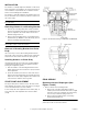
Figure-3 AV-496 Valve Linkage for MK-88XX and MK-89XX.
Figure-4 MK-8XXX Actuator Cutaway (MX-88XX Shown).
FIELD SERVICE
Replacing Actuator Diaphragms (See
Figures 3 and 4)
1. Remove actuator from mounting bracket.
a. Remove (2) connecting clamp halves between
actuator piston sleeve and valve stem sleeve. A slight
amount of air pressure supplied to the actuator may
be necessary to eliminate spring load forces.
b. Remove (2) bolts holding actuator to mounting
bracket and lift actuator up.
Note:
It is not necessary to remove mounting bracket from
valve body in order to service the actuator.