
User Guide


10 © Copyright 2008 TAC All Rights Reserved. F-23576-6
2. Slip the leads through a standard 1/2" conduit bushing (not supplied) and the knockout
hole in the cover plate. Refer to Figure-11 and Figure-12 .
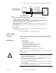
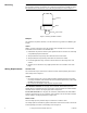
Figure-11 Conduit Bushing and Cover Plate Installation.
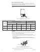
Figure-12 1/2" Conduit Bushing.
3. Nest the conduit bushing in the base.
4. Install the cover plate, using the two screws provided.
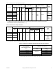
5. Make the required connections. Refer to Figure-1 through Figure-3 to determine your
particular application. Refer to Table-5 to determine the damper position versus the
input signal.
6. Attach the flexible conduit to the conduit bushing, as required.
Installing Conduit Box onto Actuator
1. Remove the knockout from the cover plate supplied with the actuator. Refer to Figure-
10 .
2. Slip the leads through a standard 1/2" conduit bushing (not supplied) and the knockout
hole in the cover plate. Refer to Figure-11 and Figure-12 .
3. Nest the conduit bushing in the base.
4. Install the cover plate, using the two screws provided.
5. Attach the conduit box to the threaded adaptor.
6. Make the required connections. Refer to Figure-1 through Figure-3 to determine your
particular application. Refer to Table-5 to determine the damper position versus the
input signal.
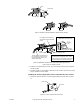
7. Install the rigid conduit, the flexible conduit, etc. to the conduit box as required. Refer to
Figure-13 .
1/2" Conduit Bushing
(not supplied)
Base
Cover Plate
1/8" maximum
Use TAC 11-1612,
Bridgeport 1102-DC,
or equivalent