
User Guide


F-23576-6 © Copyright 2008 TAC All Rights Reserved. 11
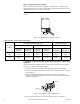
Figure-13 Attachment of Conduit Box to Threaded Adaptor.
Note:
As shown in Figure-11 , the hole in the cover plate of the actuator conduit housing is
sized to accept both British standard M20 (20 mm) conduit connectors and 20 mm-to-PG16
adaptors for use with DIN PG16 connectors. (Follow the steps for installing the conduit box
to the actuator.)
Linkage Assembly Damper
Note:
Each actuator in the MPR-5X3X series is provided with a factory-installed damper
linkage. No separately-ordered linkage is required.
Caution:
• Do not twist or exert any force on the actuator housing during installation. Either turn
the base by hand or, if necessary, use a 1-5/8" open-ended wrench (TOOL-37) on the
flats provided on the actuator base, or on the valve body mounting nut. (Refer to
Figure-4 )
1. Determine the best mounting position for the actuator as follows:
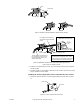
a. Determine, from the system requirements, if the damper should spring-return to the
open position (Figure-14 ) or closed position (Figure-15 ) whenever power is lost
to the actuator. An actuator is normally linked so as to retract (spring-return) to the
damper’s fully open position (heat position).
Figure-14 Dampers Open When Actuator Retracts
(Spring-Returns Open on Power Loss).
Conduit Lock Nut
Spring returns open
on loss of power
Open
Close
ExtendRetract
Damper Shaft