
User Guide


F-23576-6 © Copyright 2008 TAC All Rights Reserved. 5
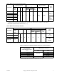
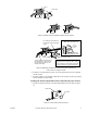
Figure-2 Wiring Diagram - Decrease in Temperature Causes Actuator Shaft to Retract.
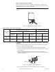
Figure-3 Wiring Diagram - 4 to 20 mAdc Controllers.
INSTALLATION
Inspection Inspect the package for damage. If damaged, notify the appropriate carrier immediately.
If undamaged, open the package and inspect the device for obvious damage. Return
damaged products.
Requirements • Job wiring diagrams
• Tools (not provided):
– Digital Volt-ohm Meter (DVM)
– Appropriate drill and drill bit for mounting screws
– TOOL-19, Spring compression tool for AV-600
– TOOL-37, 1-5/8" open-ended wrench
– TOOL-209, 135
Ω and 0 to 7 mA manual positioner
– Two 3/8" wrenches
• Training: Installer must be a qualified, experienced technician
Warning:
Disconnect power supply before installation to prevent electrical shock and
equipment damage.
Caution:
• Use electrostatic discharge precautions (e.g., use of wrist straps) during installation and
wiring to prevent equipment damage.
• Make all connections in accordance with the wiring diagram and in accordance with
national and local electrical codes.
Use copper conductors only.
• Do not exceed the ratings of the device(s).
• Do not apply power to the unit unless the damper linkage and/or the valve assembly
have been installed.
• Avoid locations where excessive moisture, corrosive fumes, or vibration is present.
• Do not install insulation on any part of the actuator.
Notes:
1. The 4 to 20 mAdc controller is supplied by others.
2. The controller has setpoint and throttling range (proportional band) adjustments. The controller may also
incorporate I (integral) and D (differential) functions.
3. To expose the startpoint adjuster, remove the plug button from the base of the actuator by prying it off with a
screwdriver. With a 4 mA controller input signal present, use a small, single-slotted screwdriver to adjust the
actuator startpoint potentiometer so that the actuator shaft just begins to extend.
4. The output can be either direct-acting or reverse-acting:
Direct-Acting (DA) Output: An increase in the measured media causes the controller output (4 to 20 mA
signal) to increase.
Reverse-Acting (RA) Output: An increase in the measured media causes the controller output (4 to 20 mA
signal) to decrease.
Sequence Of Operation:
An increase in the 4 to 20 mAdc signal causes the MPR-561X or MPR-563X actuator shaft to extend. On
power loss to the actuator, the shaft retracts.
+
-
Controller
4 to 20 mAdc
Output Signal
24Vac Black/Blue
120Vac White
240Vac White/Black
To AC Power
Source
Yellow/White
Red
Black
MPR-561X or MPR-563X
Actuator startpoint adjuster
is located behind the plug
button on the base
Green