
User Guide


F-23576-6 © Copyright 2008 TAC All Rights Reserved. 7
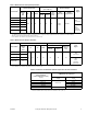
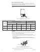
Refer to Table-4 for the maximum length of run for the power leads, for the given wire
size(s). To determine the allowable maximum power lead run when wiring multiple
actuators, divide the maximum run shown in Table-4 by the number of actuators on the run.
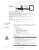
Refer to
Figure-5 for further details.
Table-4 Power Wiring Data.
Figure-5 Wiring of Multiple MPR-56XX and MPR-57XX Series Actuators to a Single Power Source.
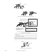
Wiring Connections General
Make connections as required. Refer to the following sections:
• Wire Lead Connections (No Conduit)
• Install 3/8" reduced (thin wall) flexible conduit onto either side of actuator
• Install 3/8" reduced (thin wall) flexible conduit directly onto actuator
• Install conduit box onto actuator
Actuator
Voltage
Vac
Actuator Model
Number
Power Lead Colors* Wire Size GA
Max. Two-Wire Run ft.
(m)
24
MPR-5613
Black/Blue & Black
14 300 (91.5)
MPR-5713
MPR-5633
12 480 (146.3)
MPR-5733
120
MPR-5610
White & Black 14 3,500 (1,067)
MPR-5710
MPR-5630
MPR-5730
240
MPR-5611
White/Black & Black 14 6,000 (1,829)
MPR-5711
*Green grounding wire is provided. Length is 4 ft. (1.2 m).
Black
Green
Green
To Additional MPR-56XX and
MPR-57XX Series Actuators
24Vac Black/Blue
120Vac White
240Vac White/Black
To AC Power
Source
MPR-56XX or MPR-57XX
Yellow/White
Red
Blue
Controller
MPR-56XX or MPR-57XX
Yellow/White
Red
Blue
Controller