
User Guide


8 © Copyright 2008 TAC All Rights Reserved. F-23576-6
Wire Lead Connections (No Conduit)
Make connections as required. Refer to Figure-1 through Figure-3 to determine your
particular application. Refer to Table-5 to determine the damper position versus the input
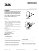
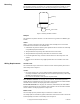
signal. Refer to Figure-6 for a view of the actuator.
Note:
The cover plate and screw supplied with the actuator are not required with this
method.
Figure-6 Connection of Wire Leads (No Conduit).
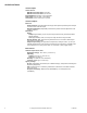
Table-5 Damper Position Versus Input Signal.
Installing 3/8" Reduced (thin) Wall Flexible Conduit onto One or Both Sides
of Actuator
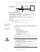
Flexible conduit may be installed onto one or both sides of the actuator (refer to Figure-8
and Figure-9 ). Install each conduit as follows:
1. Determine the side of the actuator to which the flexible conduit is to be attached.
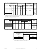
2. Remove the knockout, using channel lock pliers, on the selected side of the actuator.
Refer to Figure-7 .
3. Make the required connections. Refer to Figure-1 , Figure-2 , and Figure-3 to
determine your particular application. Refer to Table-5 to determine the damper position
versus the input signal.
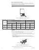
Figure-7 Removal of Knockout on Actuator Base.
4. Slip the conduit onto the base, over the ribs. Refer to Figure-8 and Figure-9 .
Damper Normal
Position
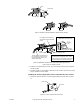
MPR-573X Series
135 Ω Slidewire (Series 90) Input Signal
MPR-563X Series
4 to 20 mA Input Signal
Figure-1 Figure-2 Figure-3
Decrease
In "R" to "B"
Resistance
Decrease
In "R" to "W"
Resistance
Decrease
In "R" to "B"
Resistance
Decrease
In "R" to "W"
Resistance
Decrease
In mA Signal
Increase
In mA Signal
Normally
Open
Closes
Damper
Opens
Damper
Opens
Damper
Closes
Damper
Opens
Damper
Closes
Damper
Normally
Closed
Opens
Damper
Closes
Damper
Closes
Damper
Opens
Damper
Closes
Damper
Opens
Damper
Base
Knockout