MS40-7043 Series MS4X-7073 Series MS4X-7153 Series TAC DuraDrive Series Spring Return Proportional Actuator General Instructions Application TAC DuraDrive™ Direct Coupled Actuators are designed to be used in both damper and valve control applications. The following general instructions are for damper applications. Refer to the Applicable Literature table for valve literature. The MS4X-7XX3 series spring return actuators provide proportional modulation control of dampers and valves in HVAC systems.
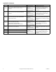
Applicable Literature F-Number Audience Purpose F-26750 – MA4X-XXXX-2XX, MF4X-XXXX-2XX, MS4X-XXXX-2XX – – Series Actuator/Linkage Assemblies General – Instructions – Sales Personnel Application Engineers Installers Service Personnel Start-up Technicians Describes the globe valve actuator/linkage assembly’s features, specifications, and possible applications. Provides step-by-step mounting instructions.
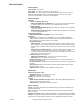
SPECIFICATIONS Actuator Inputs Control Signal: See Table-1. Power Input: See Table-1. All 24 Vac circuits are Class 2. Connections: 3 ft. (91 cm) plenum rated cable for MS40-7043-XXX and 3 ft. (91 cm) appliance cables for MS4X-7153-XXX and MS4X-7073-XXX, 1/2” (13 mm) conduit connectors. For M20 Metric conduit, use AM-756 adaptor. Actuator Outputs Electrical: Position Feedback Voltage “AO”, MS40-7043, MS4X-7153 and MS4X-7073 2 to 10 Vdc (max. 0.
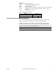
Table-1 Specifications. Approximate Timing in Seconds @ 70°F (21°C)a Actuator Power Input Part Number Holding Running Voltage 50 Hz 60 Hz VA W VA W 5.6 4.2 5.6 4.2 DC Amps Spring 50/60 Powered Return Hz No MS4X-7073502 24 Vac ± 20% 22-30 Vdc 0.15 2.4 <130 <25 MS40-7043MP MS40-7043MP5 a b c d e f Onee 5.8 4.6 5.8 4.6 0.17 2.3 <195 <30 9.8 7.4 9.7 7.4 0.28 2.9 <190 <30 Twof No 24 Vac ± 20% 22-30 Vdc Max.
MS40-7043-XXX AM-709 AM-710 AM-711 AM-712 AM-713 AM-715 AM-717 Damper Position Indicator Universal Clamp for up to 3/4" diameter shafts Crankarm for up to 1/2" round shaft Crankarm Adaptor Kit Mounting Bracket for Honeywell Mod IV, M6415 type actuators, and new installations Crankarm Adaptor Kit for Honeywell Mod IV M6415 type actuators, and new installations Replacement Universal Clamp Table-2 Auxiliary Power Supply.
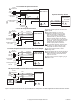
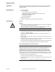
4 to 20 mAdc Proportional Control 1 24 Vac Transformer Line Volts Control Signal 4 to 20 mA (-) (+) Feedback Signal 2 to 10 Vdc 6 (-) (+) 500 Ω Gra Common Blk Common Red Hot (DC) MS40-7043 MS40-7043-501 Optional Auxiliary Switch 5 AI AO Yel/Blk Blu Aux Switch (MS40-7043-501) Grn/Yel Org Vio L R 4 Yel Com (S1) NC (S2) NO (S3) 0 to 1 Scale Adjustable 3 To Additional Actuators 2 2 to 10 Vdc Proportional Control 24 Vac 1 Transformer Line Volts (-) (+) Feedback Signal (-) 2 to 10 Vdc (+
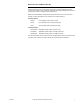
MS4X-7073-XXX and MS4X-7153-XXX Caution: This product contains a half-wave rectifier power supply. It must not be powered with transformers that are used to power other devices utilizing non-isolated full-wave rectifier power supplies. Refer to EN-206, Guidelines for Powering Multiple Devices from a Common Transformer, F-26363 for detailed information. MX40-707X-502 and MX40-715X-502 units manufactured prior to the date code 0141 (October 6, 2001) used different color coding for the auxiliary switches.
2 to 10 Vdc Proportional Control 24 Vac Transformer 1 or 22- 30 Vdc Gra Blk Com Red Hot (+DC) AI Yel/Blk Blu AO Line Volts Control Signal 2 to 10 Vdc Feedback Signal 2 to 10 Vdc Com (-) (+) (-) (+) Grn/Yel Optional Auxiliary Switches MS4X-7073 MS4X-7153 MS4X-7073-502 MS4X-7153-502 Aux Switches MS4X-7073-502 MS4X-7153-502 Org COM Vio NC NO Yel Aux Switch 1 25 to 85° Adjustable 5 L R 6 Org/Wht Vio/Wht COM NC Yel/Wht NO Aux Switch 2 5° Fixed 4 to 20 mAdc Proportional Control 24 Vac Trans
INSTALLATION Inspection Requirements Inspect the package for damage. If damaged, notify the appropriate carrier immediately. If undamaged, open the package and inspect the device for obvious damage. Return damaged products. • Job wiring diagrams • Tools (not provided): – – – – – #8 sheet metal screws (Universal Bracket) 10mm open end wrench or socket wrench (Universal V-clamp) 1/8 inch, allen wrench (Aux.
Canadian Department of Communications (DOC) Note: This Class B digital apparatus meets all requirements of the Canadian InterferenceCausing Equipment Regulations. Cet appareil numerique de la classe B respecte toutes les exigences du Reglement sur le material broilleur du Canada. European Standard EN 55022 Warning: This is a Class B digital (European Classification) product. In a domestic environment this product may cause radio interference in which case the user may be required to take adequate measures.
MS40-704X 1 .8 .6 .4 .2 L 0 Switch on R 9 R 1 .8 .6 .4 .
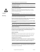
MS40-704X Series Installation Note: The MS40-704X series actuator comes equipped with standard universal mounting clamp. For damper shafts larger than 5/8" (16 mm) in diameter, the AM-710 universal mounting clamp is required (order separately). The AM-710 clamp accommodates shafts sizes up to 3/4" (19 mm) diameter shafts. Long Shaft Short Shaft Min. 3/4" (20 mm) Min. 3 1/2" (90 mm) 3/8" to 3/4" Diameter (10 mm to 20 mm) 3/8" to 1/2" Square (10 mm to 13 mm) Move the damper to its normal position.
B - Left - Long Shaft B - Right - Long Shaft 2 2 2 R 1 2 L 3 1 1 3 L 4 4 "L" Marker "R" Marker 1. 2. 3. 4. Universal 1 mounting clamp. .2 0 Universal 1 mounting clamp. Correct clamp mounting position if actuator is in normal spring return position (before preload) .4 2 Retaining clip. Assemble mounting clamp. Assemble retaining clip. Place actuator over shaft. Hand tighten clamp nuts. L B - Left - Short Shaft 2 Retaining clip. .4 .
C - Left and Right Center the Universal Bracket in the Slot 0 1 .8 .6 .4 .2 1/2 1/2 1 5 7 x1 8 6 x2 #8 Sheet Metal 1 Screw 5. 6. 7. 8. Center bracket in slot. Drill two holes. Start one screw. Swing bracket down. D- Left CL 10 0° 1 .8 .6 .4 .2 L 0 Centerline 0 D- Right CL Centerline 1 1.8 .8 .6 .6 .4 .4 .2 0.2 0 R 1 .8 .6 .4 .2 0° 10 9 9 12 12 12 14 14 5° 11 11 5° 13 13 9. 10. 11. 12. 13. 14. 14 Loosen clamp nuts. Check that the shaft is in full zero position.
E- Left E - Right 1 .8 .6 .4 .2 1 .8 .6 .4 .2 0 R L 0 9 12 15 x2 15 x2 15. Tighten bracket screws. Correct clamp mounting position (after 5˚ preload) .4 .2 0 L .4 .2 R 0 MS4X-707X and MS4X-715X Series Installation Caution: Do not drill additional holes in the actuator body. Six pre-drilled holes are located on each side, under the label, to accept #10-24 thread-forming screws for mounting accessories.
Long Shaft Short Shaft Min. 3/4" (20 mm) Min. 3 1/2" (90 mm) 3/8" to 3/4" Diameter (10 mm to 20 mm) 3/8" to 1/2" Square (10 mm to 13 mm) Move the damper to its normal position. Verify the controller action is set to match the damper application. Normally closed damper: when damper is closed, actuator position indicator should be at 0°. When damper is open, actuator position indicator should be at 90°. Normally opened damper: when damper is open, actuator position indicator should be at 0°.
C - Left - Long Shaft C - Right - Long Shaft 2 2 2 R 3 1 2 L 1 1 3 4 L 4 "L" Marker R L LOCK L R O C L K "R" Marker 1. 2. 3. 4. Universal 1 mounting clamp. Assemble mounting clamp. Assemble retaining clip. Place actuator over shaft. Hand tighten clamp nuts. Universal 1 mounting clamp. 2 Retaining clip. 2 Retaining clip.
D - Left and Right Center the Universal Bracket in the Slot R 1/2 1/2 5 6 5. 6. 7. 8. 1 x2 Center bracket in slot. Drill two holes. Start one screw. For MS41-707X and MS41-715X actuators, insert and tighten both screws. Swing bracket down (MS40 actuator only). E- Left CL #8 Sheet Metal 1 Screw 8 E- Right Centerline x1 7 CL Centerline 10 0° 0° 10 L R R R 9 9 11 11 13 L 13 R 9. Loosen clamp nuts. 10. Check that the shaft is in full zero position.
F- Left F- Right L 16 R x2 16 x2 For MS40-707X and MS40-715X only: 16. Tighten bracket screws. For MS40-707X and MS40-715X actuators: 40 30 20 10 0 -5 Correct pointer position after mounting. L 40 30 20 10 0 -5 R For MS41-707X and MS41-715X actuators: 40 30 20 10 0 -5 Correct pointer position after mounting. L 40 30 20 10 0 -5 R The lock on MS41-707X and MS41-715X will release on first power-up. F-26645-7 © Copyright 2008 TAC All Rights Reserved.
Jackshaft Installation (MS40-7043 Series) The MS40-7043 actuator is designed for use with jackshafts up to 3/4" (19 mm) in diameter. In most applications, the MS40-7043 actuator may be mounted in the same manner as a standard damper shaft application. If the jackshaft diameter is larger than 5/8" (16 mm) in diameter, the optional AM-710 universal clamp must be used. (MS4X-7153 and MS4X-7073 Series) The MS4X-7153 and MS4X-7073 actuators are designed for use with jackshafts up to 1.05" (27 mm) in diameter.
Wiring Requirements Control Leads See Table-3 for power wiring data. Refer to Figure-1 and Figure-2 for typical wiring. Table-3 Power Wiring. Actuator Voltage Maximum Wire Run in ft.
Rotation Limitation Rotation Limitation for MS40-7043 Series The Stop Block is used in conjunction with the tab on the universal clamp or the AM-709 position indicator. In order to function properly, the clamp or indicator must be mounted correctly. The Stop Block controls the rotational output of the MS40-7043 and MF40-7043-501 actuators. It is used in applications where a damper has a designed rotation that is less than 90°, for example with a 45° or 60° rotating damper.
Rotation Limitation for MS4X-7153 and MS4X-7073 Series The AM-689 rotation limiter is used in conjunction with the tab on the universal clamp or the AM-686 position indicator which comes with the AM-689. In order to function properly, the clamp or indicator must be mounted correctly. The AM-689 rotation limiter controls the rotational output of the MS4X-7153, MS4X-7153502, MS4X-7073, and MS4X-7073-502 actuators.
Minimum Damper Positioning Note: When using the AM-689 rotation limiter with an MS4X-7073 or MS4X-7153 actuator to provide a minimum damper position, the short shaft mounting procedure must be used to mount the actuator. Caution: • The AM-689 rotation limiter should not be used with an MS4X-7073 or MS4X-7153 actuator to provide a minimum damper position in outdoor air damper applications. The rotation limiter prevents the damper from reaching the full-closed position.
CHECKOUT After the entire system has been installed and the actuator has been powered up, the following check can be made for proper system operation. Check for correct operation of the damper while actuator is being stroked. 1. Apply power to the actuator. Actuator and damper should be driven to their powered position as determined by the control signal. 2. On the MS4X-7XXX-50X models, check for correct auxiliary switch operation. 3. Break power to the actuator.
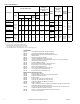
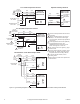
MAINTENANCE Regular maintenance of the total system is recommended to assure sustained optimum performance. The MS4X series actuators are maintenance free. FIELD REPAIR None. Replace with a functional actuator. DIMENSIONAL DATA 6-51/64 (172) 6-13/64 (157) 13/32 (10) 4 (103) 1 (25) 3-5/32 (80) 2 (50) 3-21/32 (93) 1 3 Holes for #10-24 Screws 47/64 (19) 4-57/64 (125) 49/64 (19) 2-13/32 3-1/2 (62) (61) Dimensions shown are in inches (mm). 1 1/4 (6.4) Note: These are not through holes.
3-1/2 (89) 2-25/64 (61) 4 (103) 2-7/64 (53) 6 Holes for 1 #10-24 Screws 10-1/2 (267) 7-1/2 (191) Dimensions shown are in inches (mm). 1 Note: These are not through holes. Use hardware supplied in TAC approved AM kits. Figure-10 MS4X-7073 and MS4X-7153 Spring Return Damper Actuator Dimensions. F-26645-7 © Copyright 2008 TAC All Rights Reserved.
Copyright 2008, TAC All brand names, trademarks and registered trademarks are the property of their respective owners. Information contained within this document is subject to change without notice. F-26645-7 TAC 1354 Clifford Avenue P.O. Box 2940 Loves Park, IL 61132-2940 www.tac.