
User Guide
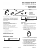

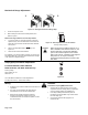
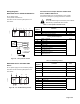
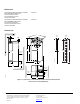
Table Of Contents

MF41-6043/MS41-6043 Series
MF41-6083/MS41-6083 Series
TAC DuraDrive Non-spring Return
Direct Coupled Actuator
Installation Instructions
Printed in the U.S.A. 9-08
F-27211-2 Page 1 of 6
Item Number 129-317-05, Rev. 013
b
e
d
f
a
45
90
90
EA0678R3
c
a. Actuator
b. Position indicator
c. Anti-rotation bracket
d. Mounting screws for anti-
rotation bracket
e. 4 mm hex key
f. Shaft insert for use with 3/8-
inch (8-10 mm) shafts
Figure 1. Parts of the TAC DuraDrive Rotary Actuator.
Product Description
These installation instructions describe the steps for direct-
coupled mounting of the TAC DuraDrive™ 35 lb-in MF41-
6043 and MS41-6043 Series, and 70 lb-in MF41-6083 and
MS41-6083 Series Non-spring Return Rotary Electronic
Damper Actuators.
Product Numbers
Three-position control: MF41-6043, MF41-6043-502,
MF41-6043-510, MF41-6083, MF41-6083-502,
and MF41-6083-510
Modulating control: MS41-6043, MS41-6043-502,
MS41-6043-520, MS41-6043-522, MS41-6083,
MS41-6083-520, MS41-6083-522, and MS41-6083-502
Required Tools
• 4 mm hex wrench
• 4 mm (5/32-inch) drill bit and drill
• Small flat-blade screwdriver
• Marker or pencil
Estimated Installation Time
30 minutes
Warning/Caution Notations
CAUTION:
Equipment damage or loss of
data may occur if you do not
follow a procedure as specified.
WARNING:
Personal injury may occur if you
do not follow a procedure as
specified.
WARNING:
Do not open the actuator.
Instructions
NOTE: Place the actuator on the damper shaft with the
front of the actuator accessible. The label is on
the front side.
1. Determine whether the damper blades will rotate
clockwise or counterclockwise to open. See
Figure 3.
2. If the blades will rotate counterclockwise, slide the
manual override switch to manual, and move the
adjustment lever to the right. Return the switch to
automatic. See
Figure 2.
45
90
90
PL0013R2
MANUAL
ADJUSTMENT
LEVER
AUTO
2
1
3
Figure 2.
3. To mount a (modulating) MS41-6043 or MS41-6083
Series actuator, set the Dual In-line Package (DIP)
switches to the required positions. See Figure 3.
4. To access the DIP switches, raise the tab on the
lower left side of the actuator's face. See Figure 3.
The factory setting is clockwise (middle switch), with
a direct-acting feedback signal (right switch).
5. Close the tab over the DIP switches.
6. To mount a (3-position) MF41-6043 or MF41-6083
Series actuator for counter-clockwise rotation,
follow the Counterclockwise Damper Rotation
instructions located in the Wiring Diagrams section
when wiring the actuator to the controller.