
User Guide


Start-Up/
Commissioning,
Continued
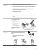
Non-spring Return
Three-position
24 Vac
5. Check Operation:
a. Apply a control signal (24 Vac) to wires 1 (red) and 6 (violet).
b. Allow the actuator shaft coupling to rotate from 0 to 90°.
c. Stop applying a control signal to wires 1 (red) and 6 (violet).
d. Apply a control signal (24 Vac) to wires 1 (red) and 7 (orange).
e. Allow the actuator shaft coupling to rotate from 90° to 0°.
Service
WARNING:
Do not open the actuator.
If the actuator is inoperative, replace the unit.
Troubleshooting
• Check that the wires are connected correctly.
• Check that auxiliary switches, DIP switches, and Offset/Span are set correctly.
• Set the DMM dial to Vac and verify that the operating voltage is within range.
• If the actuator is not working, check the damper for blockage. If blocked,
remove the obstacle and cycle the actuator power off and on. The actuator
should resume normal operating mode.
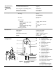
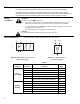
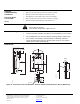
Dimensions
min. 1/2
(12)
5-9/16
(141)
8-3/8
(212)
1-11/16
(42)
1-3/16
(30)
1-3/16
(30)
1/8
(3)
min. 4
(100)
min. 6
(150)
min.2-3/8
(60)
min. 4
(100)
EA0877R2
3 ft
(900)
2-3/8
(60)
1/2" NSPT
1/2
(12)
3/4
(19)
47.5˚ 47.5˚
min. 4
(100)
3.25
(83)
25/32
(20)
7-1/16
(180)
5mm
Ø
EA0876R1
Figure 11. Dimensions of the TAC DuraDrive Actuator and Anti-rotation Bracket in Inches (Millimeters).
without notice.
F-27215-2
www.tac.com
Copyright 2008, TAC
All brand names, trademarks and registered trademarks
are the property of their respective owners. Information
contained within this document is subject to change
TAC
1354 Clifford Avenue
P.O. Box 2940
Loves Park, IL 61132-2940