
User Guide


Operation
MS41-6153 Series
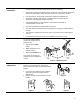
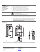
Apply a 0 to 10 Vdc control signal between wire 8 (Y) and wire 2 (G0) to operate the damper
actuator. The angle of rotation is proportional to the control signal. A 0 to 10 Vdc position
feedback output signal is available between wire 9 (U) and wire 2 (G0) to monitor the position
of the damper motor.
In the event of a power failure, the actuator holds its position. In the event that only the control
signal is lost, the actuator returns to the "0" position.
MF41-6153
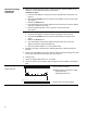
A floating control signal controls the damper actuator. The actuator’s angle of rotation is
proportional to the length of time the signal is applied. A 24 Vac control signal to wire 6 (Y1)
causes the actuator coupling to rotate clockwise. A 24 Vac control signal to wire 7 (Y2)
causes the actuator coupling to rotate counterclockwise.
To reverse the direction of rotation, wires 6 (Y1) and 7 (Y2) can be interchanged.
With no control voltage, the damper actuator holds its position.
Overload protection
In the event of a blockage in the damper, the actuator is overload protected over the full range
to prevent damage to the actuator.
Life expectancy
An improperly tuned loop will cause excessive repositioning that will shorten the life of the
actuator.
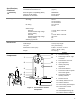
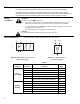
Sizing
The type of actuator required depends on several factors:
1. Obtain damper torque ratings (ft-lb/ft
2
or Nm/m
2
) from the damper manufacturer.
2. Determine the area of the damper.
3. Calculate the total torque required to move the damper:
Total Torque =
SF
AreaDamper Rating Torque
1
×
1
Safety Factor: When calculating the total torque required, a safety factor should be included
for unaccountable variables such as slight misalignments, aging of the damper, etc. A
suggested safety factor is 0.80.
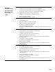
4. Select the non-spring return actuator type using Table 2.
Table 2.
Total Torque Actuator
<35 lb-in (<4Nm) MF41-6043 and MS41-6043 Series
<70 lb-in (<8Nm) MF41-6083 and MS41-6083 Series
<133 lb-in (<15Nm) MF41-6153 and MS41-6153 Series
4