
User Guide


5
Mounting and
Installation
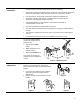
• Place the actuator on the damper shaft so that the front of the actuator is accessible.
(The label and the manual override button are on the front side.)
• The minimum damper drive shaft is 3/4-inches (20mm). The shaft length determines
whether the shaft adapter will be mounted on the front or back of the actuator.
• See Specifications for minimum and maximum damper shaft dimensions.
• Set auxiliary switches, DIP switches, and Offset/Span as required by your
application. (See following sections for details.)
• The position indicator can be mounted to show either the clockwise or
counterclockwise 0 to 90 scale.
• An anti-rotation bracket is included with the actuator.
• The shaft adapter and mounting parts are shipped in a separate container with the
actuator.
• The actuator is shipped from the factory with a 5° pre-load to ensure tight damper
close off.
• For detailed mounting instructions, see Installation Instructions F-27212.
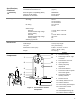
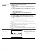
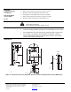
Manual Override
To move the damper blades
and lock the position with no
power present:
1. Hold down the PUSH
button.
2. Make adjustments to the
damper position.
3. Release the PUSH button.
Once power is restored, the
actuator returns to automated
control.
EA0946R1
1
3
2
PUSH
L > 3 in.
77mm
L < 2-3/8 in.
60mm
3
2
PUSH
Figure 2. Manual Override.
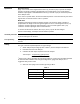
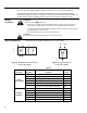
Mechanical Range
Adjustment
The angular rotation is adjustable between 0°
and 90° at 5-degree intervals. The range of
shaft movement is limited by mounting the shaft
adapter:
1. Loosen the shaft adapter from the damper
shaft and remove the actuator from the
damper shaft.
2. Remove the clip and shaft adapter from the
actuator.
EA0947R1
1
2
Figure 3.
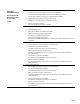
EA0948R1
90
45
90
45
EA0949R1
EA0951R1
90
45
Figure 4. Figure 5 Figure 6.