
User Guide


Mechanical Range
Adjustment,
Continued
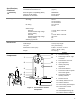
3. Return the actuator gear train to the "0" position using the steps that follow for the
clockwise or counterclockwise damper shaft rotation.
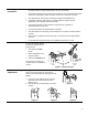
Clockwise to open:
a. Insert the shaft adapter to the right as close as possible to the raised stop. See
Figure 4.
b. Hold down the PUSH button and rotate the shaft adapter to the left until it stops.
See
Figure 5.
c. Release the PUSH button.
d. If the shaft adapter is not resting against the left raised stop, remove the adapter
and insert it against the left stop.
e. Place the position indicator to the "0" position on the outside scale.
See
Figure 6.
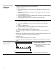
Counterclockwise to open:
a. Insert the shaft adapter to the left as close as possible to the raised stop.
b. Hold down the PUSH button and rotate the shaft adapter to the right until it
stops.
c. Release the PUSH button.
d. If the shaft adapter is not resting against the right raised stop, remove the
adapter and insert it against the right stop.
e. Place the position indicator to “0” on the inside scale.
4. Determine the angle of rotation for the damper blade shaft. Subtract that amount
from 90°.
5. Remove the shaft adapter and insert it with the position indicator pointing to the mark
on the scale calculated in the previous step. See
Figure 6.
6. Attach the clip.
7. Rotate the damper blade shaft to its "0" position.
8. Return the actuator to the damper shaft and tighten the shaft adapter to the damper
shaft.
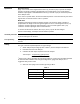
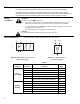
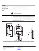
Dual Auxiliary Switch
MS41-6153-502
A
-2,5 0 10 20 30 70 80 90 92,5
B
0 10 20 30 70 80
EA0640R1
92,5 90 80 70
60
20 10
-2,5
90
0
← Actuator scale: Clockwise
Adjustment range for switches A and B:
Setting interval: 5°
Switching hysteresis: 2°
← Actuator Scale: Counterclockwise
6