
User Guide


7
Dual Auxiliary Switch,
Continued
MS41-6153-502
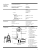
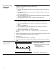
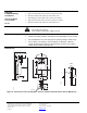
To change the settings of A and B:
NOTES:
• The scale is only valid when the actuator is in the "0"
position on clockwise motion.
• For the counterclockwise rotation, the shaft
adapter/position indicator has to move from 90° to 0°
and then adjust the auxiliary switches. After the
auxiliary switches are adjusted, the shaft
adapter/position indicator has to move back to the 90°
position.
• Use the adjustment tool provided with the actuator to
turn the switch adjustment dials to the desired signal
setting.
Factory setting:
Switch A 5°
Switch B 85°
Recommended range:
Switch A 0° to 45°
Switch B 45° to 90°
50
40
30
20
10
50
60
70
80
90
A
B
Aux Switch
Adjustment
EA0875R1
Figure 7. Dual Auxiliary
Switch Dials.
.
NOTE: Use the long arm of the "†" to point to the position of switch A. Use the narrower
tab on the red ring to point to the position of switch B.
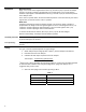
DIP Switch
Functionality
MS41-6153
MS41-6153-502
Description Label Description Function
Counterclockwise
Clockwise Rotary angle direction
Active
0 Off
Self-adaptation to
mechanical range
2 to 10 Vdc 2 to 10
0 to 10 0 to 10 Vdc
MS41-6153:
Positioning control
signal
2 to 10 or 0 to 10
Figure 8. DIP Switches.
Rotary direction
• The arrow direction must match the rotational direction of
the actuator.
• Factory setting:
Self-adapting
0
• Alternative switch-on/off for self-adaptation.
: ON
0: OFF
• Factory setting: 0
CAUTION:
When turning the self-adaptive feature on, or after a
software reset with the feature on, the actuator will
enter a five-minute calibration cycle as the actuator
adjusts to the rotation limits of the system.
A software reset happens after power on, or may be
caused by electrostatic discharge (ESD) at levels of
2kV and above.
Positioning Control Signal: (MS41-6153)
2-10 0-10
• Alternative settings:
2 to 10 Vdc
0 to 10 Vdc
• Factory setting: 0 to 10