
User Guide


Wiring
All wiring must conform to NEC and local codes and regulations.
Use earth ground isolating step-down Class 2 transformers. Do not use autotransformers.
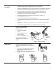
The maximum rating for a Class 2 step-down transformer is 100 VA. Determine the supply
transformer rating by summing the VA ratings of all actuators and all other components used. It is
recommended that one transformer power no more than 10 actuators (or 80% of its VA).
Wiring,
Continued
WARNINGS:
Installations requiring Conformance:
• Except for the auxiliary switches (See Warning above) all wiring for actuators must be
safety extra-low voltage (SELV) or protective extra-low voltage (PELV) per HD384.
• Use safety transformers per EN61558 with double isolation, designed for 100% duty-cycle
for supplying SELV or PELV circuits.
• Over-current protection for supply lines is maximum 10A.
CAUTION:
Do not parallel MF41-6153 actuators with any other type of actuator.
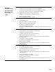
Wire Designations Each wire has the standard symbol printed on it. See Table 3.
M
A
B
S1
S4
S2 S3 S5 S6
1
8
2
9
EA0284R1
M
1
6
7
CW
CCW
PL0010R2
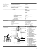
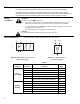
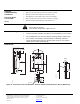
Figure 9.
Modulating 0 to 10 Vdc Control Figure 10. 3-position Control
24 Vac Power Supply
24 Vac Power Supply
Table 3.
Actuators Symbol Function Color
1 Supply (SP) Red
2 Neutral (SN) Black
6 Control signal clockwise Violet
7 Control signal counterclockwise Orange
8 0 to 10 Vdc input signal Gray
24 Vac
Power Supply
9 Output for 0 to 10 Vdc position indication Pink
S1 Switch A Common Gray/red
S2 Switch A N.C. Gray/blue
S3 Switch A N.O. Gray/pink
S4 Switch B Common Black/red
S5 Switch B N.C. Black/blue
Auxiliary
Switches
S6 Switch B N.O. Black/pink
8